


Predict post-peening Ra and Rz only within a qualified material, media, equipment and measurement domain
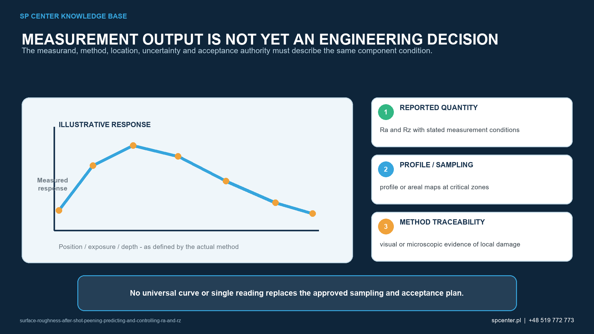
Shot peening normally changes surface topography because each particle impact plastically deforms a local area. Ra and Rz can describe parts of that change, but neither parameter alone defines isolated damage, lay, waviness, areal texture or functional suitability. There is no universal equation that converts Almen intensity, pressure or exposure time into component Ra or Rz.
Why is post-peening roughness difficult to predict?
The final texture combines the incoming machining or finishing pattern with thousands of overlapping impact impressions. Impression size and shape depend on media geometry, mass, hardness, velocity, impact angle and the plastic response of the actual material. Coverage, multiple passes and local rebound then change the impact population.
Machine settings are indirect inputs. Equal pressure on two nozzle systems or equal wheel speed on two wheel machines does not guarantee equal particle velocity, angle distribution or media flow. Even equal Almen intensity does not require equal surface topography.
| Input | Typical influence to investigate | Control boundary |
|---|---|---|
| Incoming texture and lay | Machining grooves, polishing, scale and prior blasting can remain visible or interact with impact craters | Measure the defined pre-peen condition at controlled locations; do not compare different starting finishes as one population |
| Material and near-surface hardness | Harder or case-treated surfaces can respond differently from soft, thin or heterogeneous layers | Qualify the actual alloy, heat treatment, case, coating-free condition and allowed hardness range |
| Media size, shape, hardness and density | Impact footprint and plastic deformation change with particle geometry and mechanical properties | Use the approved media family and operating mix; monitor broken, angular, oversized, undersized and foreign particles |
| Particle velocity and impact angle | Normal and tangential deformation components change with speed, angle and local geometry | Control the physical stream through qualified equipment settings, angle, distance, path and component motion |
| Coverage and cumulative exposure | Early exposure increases crater population; additional passes can overlap impressions and accumulate cold work | Meet the specified coverage and exposure without assuming that more time produces a smoother or safer surface |
| Downstream operations | Cleaning, grinding, polishing, coating preparation and thermal cycles can alter measured texture or remove the peened layer | Define whether acceptance applies immediately after peening or after the complete manufacturing route |
Table 1. Roughness arises from coupled incoming, impact and sequence variables.
How do media variables affect surface texture?
Within a controlled comparison, particle size affects the footprint of each impression. Shape defects and broken or angular particles can cut or create sharper features instead of producing the intended rounded impact. Media hardness and density interact with component hardness and velocity to change deformation.
Do not select a fine medium solely to reduce Ra. It must still be permitted, able to deliver the required intensity, reach the geometry, maintain a controlled operating mix and avoid contamination or embedment. A media substitution is a process change, not a cosmetic adjustment.
How do intensity, angle and coverage interact?
Higher particle energy can increase plastic deformation, but intensity is a standardized stream response rather than a roughness parameter. Oblique impact changes normal and tangential deformation and can leave a different texture from nominally normal impact. Curved surfaces, recesses and edges therefore need local trials.
Coverage describes the specified surface covered by impact impressions under the approved method. After full coverage, extra exposure does not redefine texture acceptance and does not necessarily smooth the surface. It can accumulate overlap, cold work and damage.
Are Ra and Rz enough for functional acceptance?
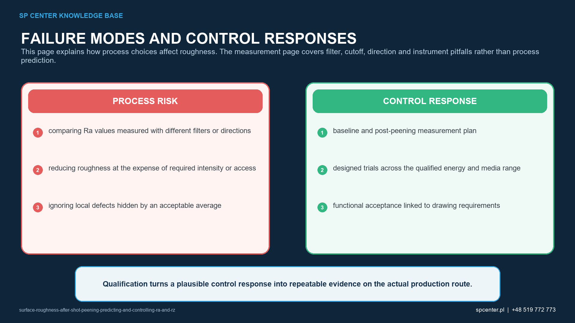
Ra is an average profile parameter; Rz describes a height characteristic under the invoked profile standard and evaluation conditions. Averages can conceal an isolated sharp valley, fold or edge defect. Parameter symbols also do not make results comparable when filtering, evaluation length, direction or instrument differs.
Areal parameters such as Sa or Sz can add spatial information when the drawing or qualification plan requires them, but an areal scan is not automatically superior. The method must resolve the relevant feature and be correlated to the functional decision.
| Functional concern | Why Ra alone is insufficient | Additional evidence to consider |
|---|---|---|
| Fatigue | An average height value does not reveal a rare fold, sharp valley, residual-stress profile or crack origin | Local damage inspection, Rz or other specified texture parameters, residual-stress and representative fatigue evidence as required |
| Sealing | Leakage can follow connected valleys or waviness that an average does not describe | Profile direction, waviness, contact band and functional sealing test |
| Bearing or sliding contact | Peak shape, spacing, material ratio and direction influence contact and lubricant retention | Specified profile or areal parameters plus contact and tribological validation |
| Coating or bonding | A rougher surface can aid mechanical keying yet harm thickness uniformity, coverage or defect risk | Qualified pretreatment, cleanliness, coating adhesion and full-system performance |
| Dimensional or thin-wall stability | Texture amplitude is not macroscopic distortion or edge movement | Independent dimensional, shape and thickness checks |
| Appearance | Gloss and reflectivity can change without a proportional change in functional texture | Controlled visual standard only where appearance is an invoked requirement |
Table 2. Functional acceptance often needs evidence beyond one roughness value.
How should a predictive model be developed?
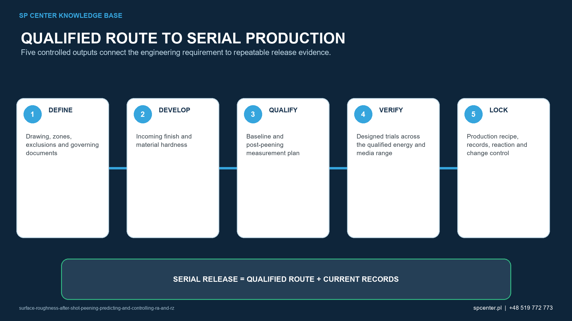
Begin with a fixed measurement system and production-representative material, incoming finish, geometry, media, machine, fixture and motion. A designed experiment can then vary a safe range of energy, media and exposure variables while measuring roughness, surface integrity, intensity, coverage and dimensions.
Regression, response-surface or machine-learning models are local empirical tools. Their uncertainty and validation domain must be reported. Do not extrapolate to a different alloy, hardness, media family, nozzle, wheel, geometry or instrument without new evidence.
| Development step | Required evidence | Decision |
|---|---|---|
| Define the surface requirement | Functional surface, process stage, parameter, limit, measurement location, direction and operator | Resolve ambiguous Ra or Rz callouts before choosing a peening recipe |
| Establish the baseline | Incoming texture distribution, material and hardness condition, measurement-system verification | Separate starting-surface variation from peening variation |
| Run a designed process trial | Production-representative media, equipment, geometry and motion across a safe qualified domain | Estimate local effects and interactions without extrapolating beyond tested conditions |
| Verify all outputs | Intensity, coverage, roughness or topography, local surface integrity, dimensions and any function-specific test | A smoother result is unacceptable if peening or component requirements fail |
| Freeze the control plan | Approved media operating mix, process window, locations, sampling, reaction limits and change triggers | Use statistical monitoring only after the measurement system and process are stable |
| Manage change | Review of media, supplier, machine, nozzle or wheel, fixture, program, material, geometry and measurement changes | Revalidate the predictive relationship whenever a controlling input changes |
Table 3. Prediction becomes production control only after both process and measurement systems are fixed.
How is roughness controlled in serial production?
Control incoming surface and material family, media operating mix, machine condition, mass flow, pressure or wheel settings, nozzle or wheel geometry, angle, distance, path, motion, coverage and exposure. Verify roughness at defined component locations with the same approved measurement conditions used during qualification.
A capability index or control chart is meaningful only when the process distribution is stable and the measurement system is capable. The reaction plan distinguishes measurement error, incoming-surface shift, media-condition change, equipment drift and access or motion failure before deciding on product disposition.
How should downstream operations be handled?
Cleaning, polishing, coating preparation, plating, thermal curing and machining can change topography or remove part of the peened layer. The drawing and qualification plan state the process stage at which roughness applies. If acceptance is required after the complete route, qualify that route rather than only the immediate post-peen surface.
Never reduce roughness at the expense of required intensity, coverage or residual layer without controlled authority. If requirements conflict, pause and obtain design or customer clarification.
What belongs in the roughness control record?
- Part, batch, material, heat treatment and incoming-finish traceability.
- Approved media, operating mix, equipment, fixture and motion program.
- Current saturation and intensity evidence plus coverage acceptance.
- Measurement standard, parameter, filter or operator, direction, location and process stage.
- Instrument, verification or calibration status and raw profile or areal data where required.
- Local surface-integrity and dimensional results.
- Statistical monitoring, alarms, reaction and product containment.
- Changes, requalification, deviations and final release.
Frequently asked questions
Can Ra or Rz after shot peening be predicted from Almen intensity?
Not by a universal conversion. The same Almen intensity can be produced with different media and particle conditions that create different component topography. Use component-specific trials within a controlled process domain.
Does smaller shot always produce a smoother surface?
Smaller rounded media can produce smaller individual impressions in a qualified comparison, but velocity, hardness, density, shape, operating mix, material and prior texture also matter. It is not a standalone selection rule.
Does longer exposure reduce roughness by evening out the surface?
Not reliably. Additional impacts can overlap impressions, increase cold work, roughness or folding, and damage sensitive features. Exposure follows the approved coverage and process window.
Is a lower Ra always better for fatigue?
No. Fatigue depends on local defects, residual stress, cold work, geometry, loading and environment as well as texture. A low average can conceal a harmful isolated valley or fold.
Can Ra measured in different directions be compared?
Only when the invoked method and measurement conditions permit it. Direction, filtering, evaluation length, instrument and location can change the result, especially when machining lay remains under peening texture.
Can optical and stylus measurements be used interchangeably?
Not without correlation. Instrument physics, lateral resolution, tip or optical response, filtering and missing-data treatment can produce different results on steep peened topography.
Can polishing after shot peening solve a roughness nonconformance?
Only through an approved sequence. Polishing removes material and may reduce the peened layer, change residual stress, dimensions or coverage evidence. Requalification and renewed acceptance may be required.
What should an RFQ state about post-peening roughness?
State the controlled drawing, material and heat treatment, incoming finish, treatment zones, peening requirements, parameter and limit, measurement standard, instrument or method, direction, location, process stage, sampling and functional constraints.
Key takeaways
- Ra and Rz cannot be predicted from intensity or pressure alone.
- Control incoming texture, material, media condition, impact geometry and exposure together.
- Use local trials and state the model’s validated domain and uncertainty.
- Do not treat a lower average roughness as automatic fatigue improvement.
- Fix measurement conditions before comparing or statistically monitoring results.
- Qualify every polishing, coating or thermal step that can change the peened surface.
Related SP Center guides
- Measuring Surface Roughness After Shot Peening
- Shot Size in Shot Peening
- Dimensional Change After Shot Peening
- Shot Peening and Fatigue Life
Technical sources
3. SAE J2441_202511: Shot Peening, stabilized November 2025
4. SAE AMS2431E: Peening Media, General Requirements, revised April 2023
5. SAE J2277_202301: Shot Peening Coverage Determination, revised January 2023
6. SAE ARP7488: Peening Design and Process Control Guidelines, issued January 2018
7. Tange, Study on Optimizing a Shot-Peening Process, SAE 2005-32-0087
Standards note: Use the complete surface-texture and peening revisions invoked by the drawing, contract and customer flow-down. This guide does not create a universal roughness limit.
Author: Paweł Kmieć
Discuss roughness control after shot peening: +48 519 772 773 | [email protected]