


Mechanisms, limits and an evidence chain for residual stress, surface integrity and component-level fatigue validation
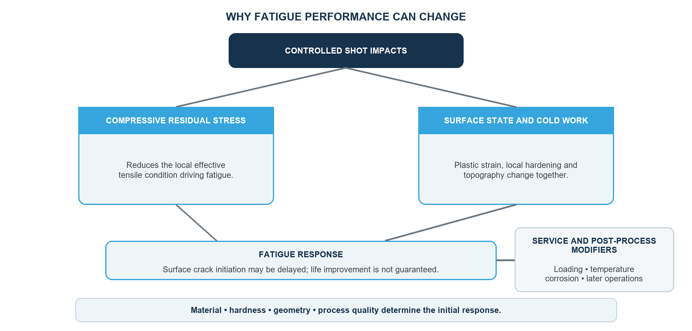
Shot peening can improve the fatigue resistance of a metal component by creating a controlled near-surface compressive residual-stress state, changing the locally cold-worked layer and modifying surface topography. The result is not automatic. Benefit depends on the material state, geometry, incoming surface, load spectrum, environment, qualified process window and stability of the treated layer. Almen intensity and coverage control the process; they do not by themselves prove a fatigue-life increase.
How does fatigue damage begin?
Fatigue develops under repeated or fluctuating load, often from a surface or near-surface discontinuity where local tensile stress and strain are high. Machining marks, grinding damage, corrosion pits, fretting, inclusions, edges, holes, fillets and other stress concentrations can become initiation sites. After initiation, a crack can propagate with each damaging cycle until the remaining section cannot carry the load.
The relevant mechanism varies with material, microstructure, mean stress, load amplitude, multiaxiality, spectrum, temperature and environment. A process claim therefore needs a defined component and failure mode. “Improves fatigue life” without this basis is an engineering hypothesis, not a release criterion.
How can shot peening influence fatigue?
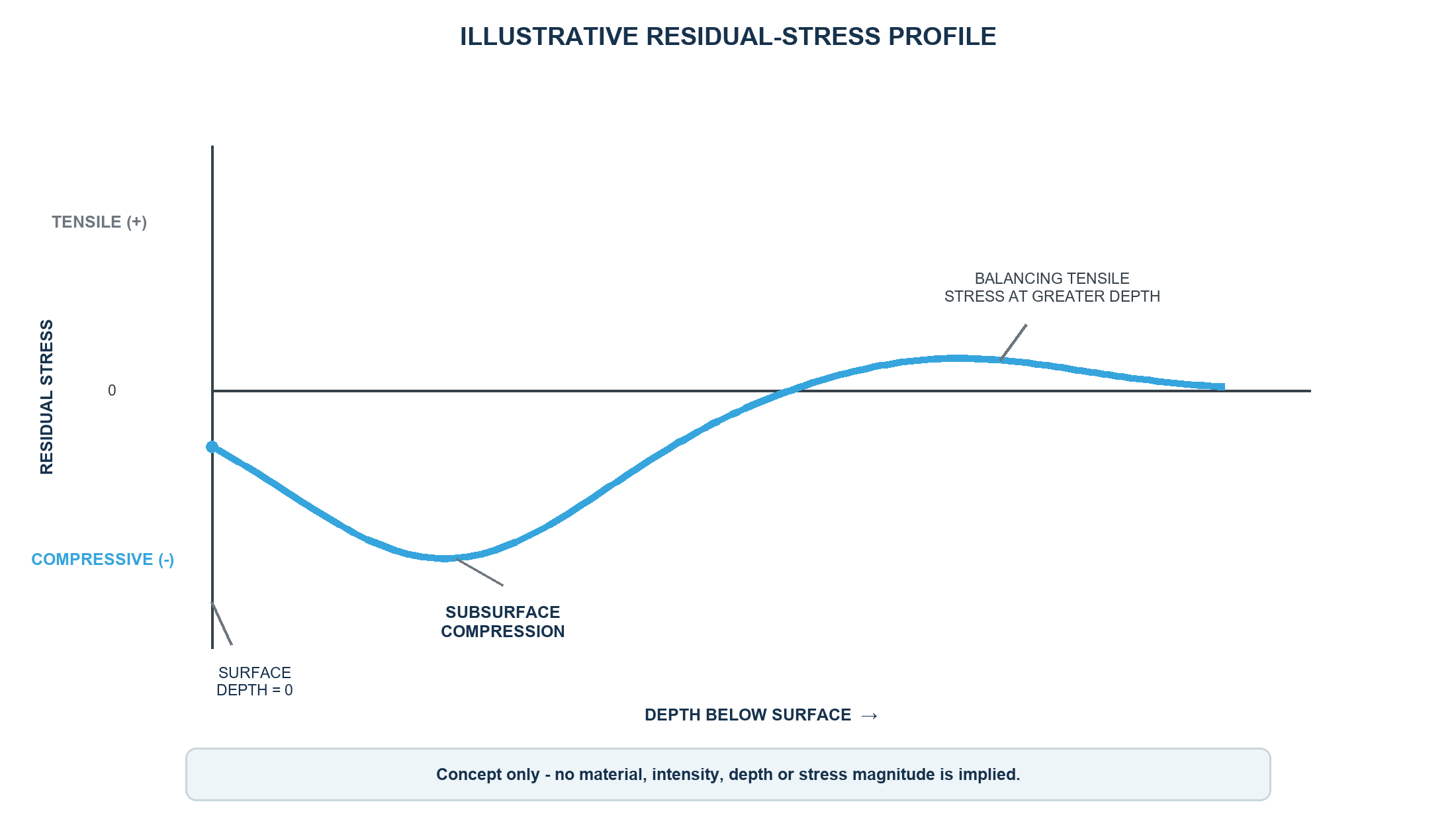
Each controlled media impact produces local plastic deformation. The underlying material constrains the plastically extended surface layer and, after unloading, a compressive residual-stress field can remain near the surface. Applied tensile load must first overcome part of this compressive state before the local surface experiences the same effective tensile condition as an untreated surface.
The impacts also cold-work the surface region and alter its topography. These effects can support or oppose the intended result. A suitable residual-stress profile can delay crack initiation, while excessive roughness, laps, microcracking, embedded contamination or edge damage can create new stress raisers. The qualified route must balance these responses.
| Effect near the surface | Potential fatigue influence | Condition or risk to control |
|---|---|---|
| Compressive residual stress | Can reduce the effective tensile driving force for surface-crack initiation and early propagation | Magnitude, depth, location, stability and balance with tensile stress elsewhere |
| Plastic deformation and cold work | Can raise local resistance to plastic strain in some material states | Excessive deformation, brittle response, retained austenite transformation or instability under service |
| Impact topography | Can remove some machining directionality and create a repeatable texture | Roughness, laps, microcracking, edge damage, coating or sealing function |
| Treatment of stress concentrations | Can place the intended state at fillets, roots, holes or transitions where fatigue demand is high | Access, impact angle, shadowing, masking boundary and local coverage |
| Manufacturing sequence | Can retain the treated layer through final manufacture and service | Later material removal, thermal exposure, straightening, blending or aggressive finishing |
Table 1. Fatigue response depends on interacting surface and subsurface effects.
Why is there no universal fatigue-life multiplier?
The untreated baseline is not constant. A polished laboratory specimen, a ground gear root, a cast surface and a corroded service component begin with different topography, defects and residual stresses. A process that helps one condition can have a smaller benefit—or be unacceptable—for another.
Service loading also matters. High mean tensile stress, overload, contact load, fretting, temperature, corrosion and long dwell periods can change crack driving force or relax the compressive state. The location and depth of maximum service stress must be considered against the depth and stability of the peened layer.
Which process variables matter most?
- Media: type, size distribution, hardness, shape, density, cleanliness and working condition influence impact energy and surface response.
- Almen intensity: verifies the qualified stream under the applicable test arrangement; the complete range and strip designation must be defined.
- Coverage and exposure: determine whether the required surface is fully treated and whether additional qualified exposure is applied.
- Geometry and impact conditions: access, angle, standoff, rebound, shadowing, nozzle or wheel pattern, fixture and part motion influence local treatment.
- Incoming condition: alloy, product form, heat treatment, hardness, case, machining, grinding, coating and damage establish the response basis.
- Sequence: later machining, grinding, polishing, heat or repair can remove, damage or relax the treated layer.
Higher pressure, wheel speed, media flow, exposure or Almen intensity is not automatically better. An overly severe route can increase roughness, distortion and surface damage or alter sensitive hardened layers. A lower setting can leave insufficient depth or fail the design basis. Development must stay within the governing requirement and use component-relevant evidence.
How do Almen intensity and coverage relate to fatigue?
Almen intensity provides standardized process evidence at a defined witness position. It does not measure component residual stress, and the same nominal intensity can be produced by different media and impact conditions with different surface responses. Media and configuration therefore remain part of the qualified basis.
Coverage confirms impact evidence across the specified component surface under an approved inspection method. Complete coverage is important because an untreated local area at a critical stress concentration can remain an initiation site. Additional exposure does not correct shadowing or an inaccessible feature and does not automatically increase life.
How should residual stress be measured?
X-ray diffraction is commonly used to characterize near-surface residual stress in crystalline materials. A meaningful requirement identifies the component or specimen, location, direction, surface preparation, method, reporting convention and acceptance logic. A surface value alone does not describe the depth profile.
Depth profiling normally combines measurements with controlled layer removal. The removal method, increments and any stress-relaxation correction must be documented because the act of removing material can change the measured state. Comparisons are valid only when geometry, method and analysis are sufficiently consistent.
How should fatigue performance be validated?
A validation plan begins with the engineering decision: comparative screening, process-window selection, design allowables, part qualification or production surveillance. It then defines untreated and peened conditions, material and heat-treatment lot, geometry, surface finish, loading direction, stress concentration, mean stress or load ratio, spectrum, frequency, environment, sample size, run-out and failure definition.
Coupons are useful only when they represent the critical mechanism. If the component’s fillet, contact condition, residual-stress redistribution, support or manufacturing sequence cannot be represented, subcomponent or full-component evidence may be required. Results should not be transferred to another alloy, hardness, geometry or process window without an authorized technical basis.
| Evidence layer | Representative method | Question answered |
|---|---|---|
| Peening-stream verification | Almen system, media condition, equipment configuration, monitored inputs and records | Was the qualified process stream reproduced? |
| Component-surface acceptance | Approved coverage inspection, boundary review, visual surface acceptance, roughness and dimensions when invoked | Was the specified surface treated and left acceptable? |
| Residual-stress characterization | X-ray diffraction at defined locations and, when required, a controlled depth-profile method | What residual-stress state exists in the evaluated direction and depth? |
| Material-state characterization | Hardness, microstructure, cold-work indicator or damage examination when required | Did the route alter the material state within the accepted basis? |
| Fatigue validation | Representative coupons, subcomponents or components under defined load spectrum, environment and statistical plan | Does the qualified route support the authorized fatigue objective? |
| Service surveillance | Field data, teardown, inspection findings and controlled feedback | Does production and service behaviour remain consistent with the approved basis? |
Table 2. Process control, surface acceptance and component validation answer different questions.
How can the compressive state be lost?
Residual stress can redistribute or relax under thermal exposure, cyclic plasticity, overload, aggressive material removal, straightening or subsequent mechanical treatment. The extent depends on material state, temperature, time, load and depth profile. A room-temperature measurement immediately after peening does not automatically describe the state after coating cure, heat treatment or service.
The manufacturing sequence should identify every later operation that can remove or alter the treated layer. If the design relies on the compressive state after such an operation, validation should represent the final condition and relevant service exposure.
What are common failure modes in development?
- Using Almen intensity as a direct residual-stress or fatigue measurement.
- Claiming a fixed percentage improvement without a defined baseline and test.
- Increasing exposure to compensate for inaccessible or shadowed geometry.
- Ignoring roughness, edge damage, contamination or dimensional effects.
- Validating a coupon that does not represent material, geometry, loading or sequence.
- Applying one qualified route after an unreviewed change in media, machine, fixture or heat treatment.
- Testing immediately after peening while service includes stress-relaxing heat or overload.
What should an engineering specification contain?
Define the current drawing and material condition, treatment and exclusion zones, governing process documents, complete Almen range and strip designation, coverage or exposure, permitted media, masking and cleaning, critical geometry, surface and dimensional acceptance, required residual-stress or fatigue validation, records, nonconformance route and change approval. If the design basis is incomplete, stop the affected decision and obtain controlled clarification.
Frequently asked questions
Does shot peening always increase fatigue life?
No. The outcome depends on material and heat treatment, geometry, incoming surface, load spectrum, environment, process window, coverage, surface damage and residual-stress stability. A universal multiplier is not technically defensible.
Why can compressive residual stress help?
Many fatigue cracks initiate or grow under tensile driving force at or near the surface. A suitable compressive residual-stress field can reduce the effective tensile condition during part of the load cycle, delaying initiation or early growth within its stable depth.
Is Almen intensity a measurement of residual stress?
No. The Almen system standardizes the response of a test strip to the peening stream. It does not directly measure the residual-stress magnitude or depth profile in the component.
Does 200% coverage double fatigue life?
No. Where invoked, 200% normally describes twice the qualified exposure used to reach complete coverage under unchanged conditions. It is not a life multiplier and can increase roughness or damage risk if the route is unsuitable.
Can higher intensity always improve fatigue performance?
No. Increasing intensity changes impact severity and can deepen the affected layer, but may also raise roughness, distortion or local damage. The acceptable window must be developed and validated for the component.
How is the residual-stress profile checked?
X-ray diffraction can characterize stress at defined locations and directions. Depth profiling generally requires controlled layer removal and a documented analysis method. Sampling, direction, removal increments and corrections must be specified.
Can shot peening repair cracks or grinding burn?
No. It must not be used to conceal cracks, grinding burn, overheating, decarburization or another unacceptable incoming condition. Such findings require evaluation and authorized disposition before peening.
When is fatigue testing needed?
It is needed when the design, customer, qualification plan or risk basis invokes part-level evidence. Test geometry, surface condition, load ratio, spectrum, environment, run-out, sample size and acceptance logic must represent the intended decision.
Key takeaways
- Shot peening can delay fatigue damage through a suitable and stable near-surface state.
- Residual stress, cold work and topography must be considered together.
- No universal fatigue-life multiplier is defensible.
- Almen intensity and coverage are process controls, not component-life measurements.
- Validate the actual material, geometry, manufacturing sequence, loading and environment.
- Control every later operation that can remove or relax the treated layer.
Related SP Center guides
- What Does Shot Peening Do to a Metal Surface?
- Shot Peening of Steel Components
- Almen Intensity in Shot Peening
- Shot Peening Coverage
Technical references
1. SAE AMS2430U: Shot Peening, revised April 2018
2. SAE ARP7488: Peening Design and Process Control Guidelines, issued January 2018
3. SAE J442_202602: Tools for Peening Intensity Determination and Verification, revised February 2026
4. SAE J443_202512: Procedures for Determining and Verifying Peening Intensity, revised December 2025
5. SAE J2277_202301: Shot Peening Coverage Determination, revised January 2023
Standards note: The complete revisions and customer-specific requirements invoked by the contract govern.
Author: Paweł Kmieć
Discuss a fatigue-critical component: +48 519 772 773 | [email protected]