


Accept the weld first, distinguish the post-weld treatment correctly and validate the toe-specific balance of residual stress, geometry, roughness and fatigue loading
Shot peening a welded joint can modify residual stress, cold work and surface condition near a fatigue-critical weld toe. It cannot repair cracks, lack of fusion, incomplete penetration, porosity, unacceptable undercut or an unsuitable weld profile. The weld must first satisfy its welding, drawing and inspection requirements. Only then can a controlled shot peening process be qualified for the actual joint geometry and loading.
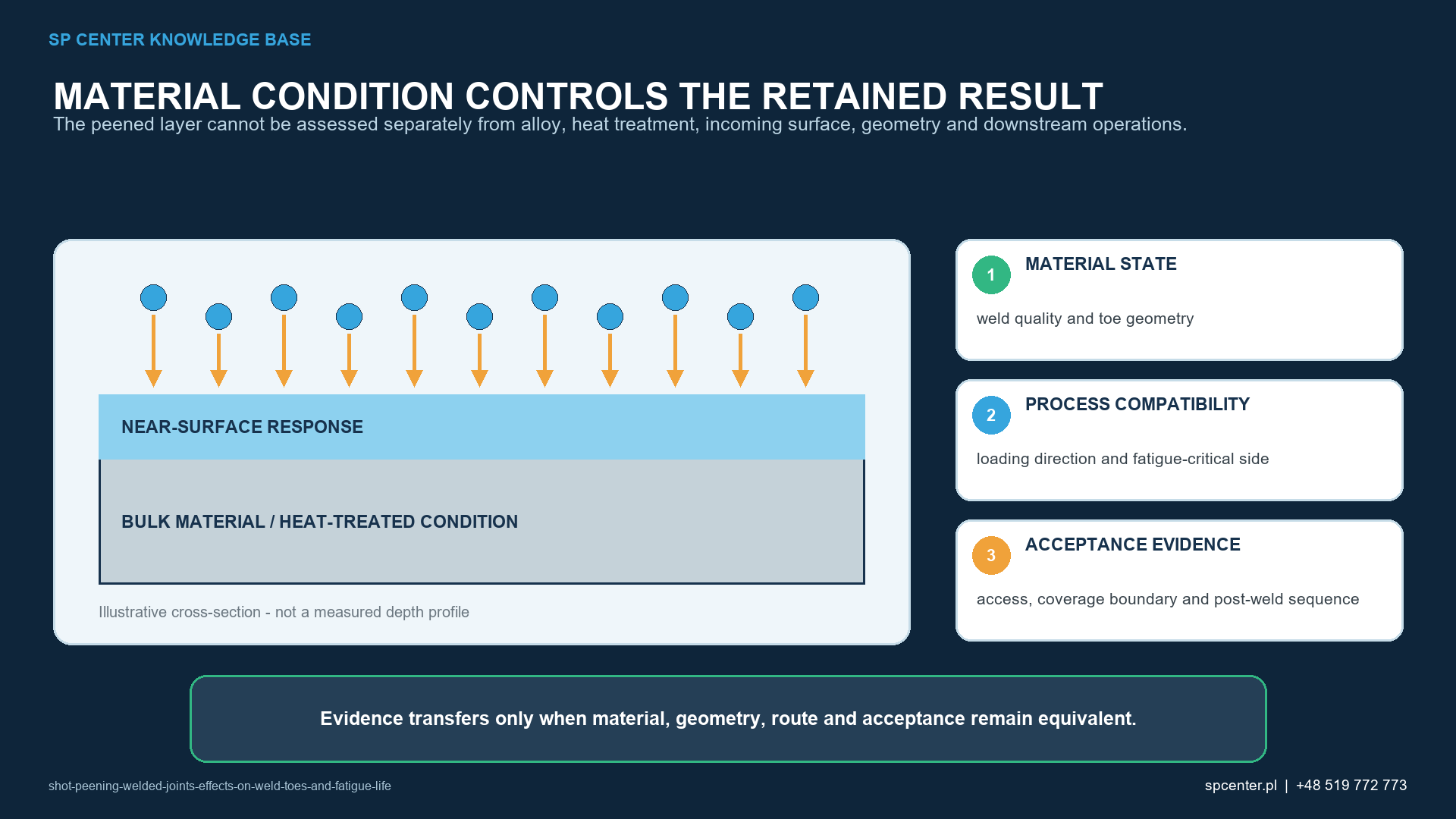
Why do fatigue cracks often start at a weld toe?
The weld toe combines a geometric stress concentration with local metallurgical variation, welding residual stress, surface irregularity and possible angular misalignment. The crack-driving condition depends on joint type, weld profile, plate thickness, loading direction, stress ratio and defect state.
Shot peening may introduce compressive residual stress and cold work, but it does not automatically improve the toe radius. Its benefit can be reduced by roughness, folds, local overexposure or relaxation under high mean stress or cyclic plasticity.
| Observed condition | Can shot peening repair it? | Required action before peening |
|---|---|---|
| Acceptable weld toe with fatigue-critical geometry | It can modify the near-surface stress and cold-work state but does not remove the notch | Define the treatment zone and qualify surface, residual-stress and fatigue response |
| Crack or crack-like indication | No | Stop, evaluate under the applicable welding and inspection rules and use only an authorized repair route |
| Lack of fusion or incomplete penetration | No | Disposition or repair under the welding procedure and design authority |
| Porosity, slag inclusion or unacceptable undercut | No | Compare with acceptance criteria; do not conceal the indication by peening |
| Arc strike, grinding burn or sharp repair mark | No | Inspect and disposition the metallurgical or geometric damage before treatment |
| Permitted toe dressing or profile improvement | Not by assumption | Use the explicitly approved grinding, TIG dressing, HFMI or other qualified procedure |
Table 1. Weld defects and an acceptable fatigue-critical toe require different actions.
Which weld condition is required before peening?
Complete the specified visual, dimensional and customer-specified inspections outside SP Center's service scope before the surface appearance is changed. Record joint type, base and filler material, welding procedure, heat input or other required variables, weld profile, distortion, repair history and accepted indications.
If an indication exceeds the acceptance criteria, stop. Repair or concession requires the authorized welding and design route. Peening is not a substitute for weld acceptance.
How is shot peening separated from other post-weld treatments?
| Process | Primary action | Why it is not interchangeable |
|---|---|---|
| Controlled shot peening | Distributed particle impacts create compressive residual stress and cold work over a defined surface | Requires Almen intensity, media, coverage and process-specific qualification |
| Blast cleaning | Removes scale or contamination and prepares a surface | Cleaning media and acceptance do not establish controlled shot peening |
| HFMI or needle/hammer peening | Repeated tool impacts plastically reshape and compress the weld-toe region | Tool geometry, groove profile, operator technique and IIW or customer rules differ |
| TIG dressing | Remelts the weld toe to improve geometry | Thermal process with welding-procedure, metallurgy and inspection implications |
| Burr grinding | Mechanically removes material and smooths the toe | Changes geometry by material removal and needs its own depth, profile and defect controls |
Table 2. Similar business objectives do not make post-weld processes technically equivalent.
Use the process named by the drawing or approved engineering plan. Do not apply HFMI quality rules to air-blast shot peening or call abrasive cleaning a fatigue-qualified peening process.
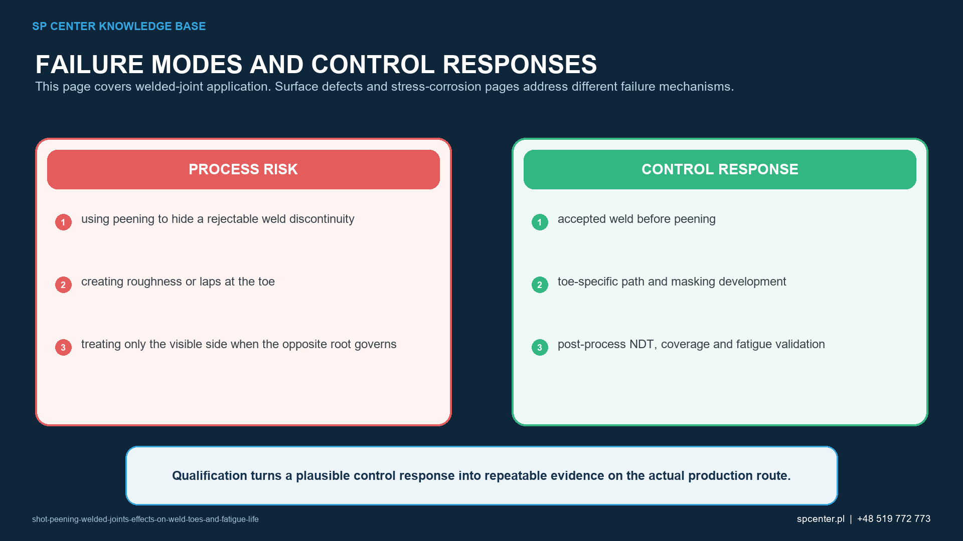
How is the weld-toe treatment zone defined?
Map the toe on every relevant side, start and stop location, attachment end, crossing and transition. Define toe width, adjacent base and weld-metal bands, protected surfaces, root accessibility, fixture contact and masking boundaries.
The stream must reach the toe at a qualified incidence without leaving a narrow untreated line. Robot path or nominal dwell does not prove local particle impact. Use a coverage method appropriate to the rough and curved geometry.
Which parameters require qualification?
Control media material, size, hardness and shape; intensity from a valid saturation curve; flow, pressure or wheel settings; nozzle or wheel geometry; angle, distance, speed, overlap and exposure. Select a window that produces the intended response without folds, sharp indentation, cracking or unacceptable roughness.
The Almen system measures standardized process response, not toe residual stress. A flat strip cannot reproduce weld geometry, heat-affected-zone properties or local access.
How are residual stress and fatigue benefit evaluated?
Residual-stress measurement at a weld toe is sensitive to location, direction, curvature, phase and surface condition. State the method, coordinate system, depth procedure and uncertainty. Surface compression at an accessible point does not establish the complete toe field.
Fatigue qualification should represent joint type, toe profile, thickness, material, loading direction, stress ratio, spectrum and environment. Record runouts, failures and fracture origins. If cracks move from the treated toe to the root or another feature, that shift matters to the design claim.
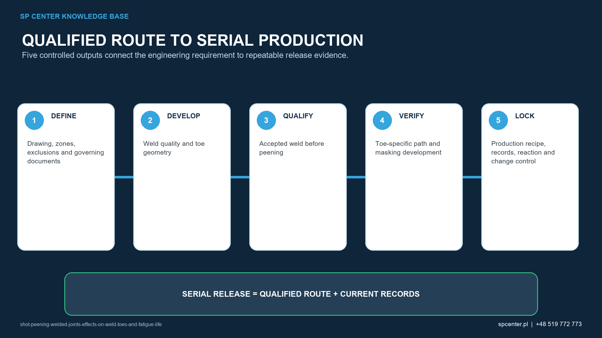
Which evidence supports release?
| Evidence layer | Suitable evidence | Claim supported |
|---|---|---|
| Weld acceptance | Applicable customer-specified inspections outside SP Center's service scope, visual profile, dimensions, material and welding traceability | Joint was acceptable before peening |
| Peening execution | Valid saturation curve, intensity verification, media, equipment, fixture, masking and coverage | Approved post-weld peening process was executed |
| Toe surface integrity | Magnified inspection, replicas or topography, roughness and damage assessment | No unacceptable folding, cracking, sharp indentation or missed toe band |
| Residual-stress response | Qualified measurement at defined toe locations, directions and depth where required | Intended near-surface state was produced |
| Fatigue performance | Representative joint fatigue tests across relevant stress ratio and fracture-origin analysis | Specific joint class, material and loading support the claimed benefit |
| Stability | Cyclic or thermal relaxation evidence where service or post-processing can change the stress state | Benefit remains relevant after the complete route and loading |
Table 3. Process conformity and fatigue-design credit are related but separate evidence layers.
Do not apply a universal improvement factor. Published results vary with processing parameters and joint conditions. Any increase in a fatigue class or design allowable must come from the governing design method and authorized qualification basis.
How do sequence and relaxation affect the result?
Grinding, TIG dressing, heat treatment, cleaning, coating and baking can change geometry, residual stress or surface condition. Qualify the complete sequence. Material removal after peening can remove part of the treated layer; heating or high cyclic stress can relax the compressive field.
Changes to weld procedure, strength class, joint type, thickness, toe treatment, media, intensity or post-peen thermal cycle require review before use.
What belongs in the control plan?
- Weld identity, procedure, material, joint and inspection traceability.
- Accepted pre-peen profile, customer-specified inspections outside SP Center's service scope and repair status.
- Controlled toe, adjacent, protected and transition-zone map.
- Qualified equipment, media, intensity, fixture and program.
- Feature-specific coverage and surface-integrity inspection.
- Residual-stress or fatigue evidence where the claim requires it.
- Complete post-peen operation and relaxation sequence.
- Deviations, rework, customer approvals and final release.
Frequently asked questions
Can shot peening close or repair a weld crack?
No. A crack remains a crack even if impacts alter its appearance. Stop and use the applicable inspection, engineering disposition and qualified weld-repair route.
Is shot blasting a weld the same as shot peening it?
No. Blast cleaning targets cleanliness or scale removal. Controlled shot peening targets a qualified process response with specified media, intensity and coverage.
Is HFMI the same as shot peening?
No. Both use mechanical impact, but HFMI uses a high-frequency tool at the weld toe and has different geometry, equipment, operator and quality criteria.
Does shot peening remove weld-toe undercut?
No. Undercut is a geometric discontinuity. Its acceptance or repair follows the welding and design requirements; peening cannot be used to hide it.
Can published fatigue improvement be used as a design factor?
Only when the applicable design code or authority accepts a qualified basis for the actual joint, material, treatment, loading and failure mode. A literature percentage is not universal.
Why does load ratio matter?
Mean tensile stress and cyclic plasticity can reduce the effective benefit or relax compressive residual stress. Qualification should represent the service stress ratio and spectrum.
Must the weld root be peened?
Only if it is accessible and required by the design and approved procedure. An inaccessible root cannot be assumed treated because the toe is covered.
When is post-peen customer-specified inspections outside SP Center's service scope required?
Follow the complete drawing, welding code, specification, customer and repair requirements. Peening can change surface appearance, so the inspection sequence must be planned before processing.
Key takeaways
- Accept the welded joint before changing its surface appearance.
- Do not use shot peening to hide or repair weld defects.
- Separate shot peening from cleaning, HFMI, TIG dressing and grinding.
- Qualify toe access, coverage, intensity and surface integrity.
- Match fatigue evidence to joint geometry, stress ratio and fracture origin.
- Control post-peen thermal and cyclic relaxation.
Related SP Center guides
- Shot Peening and Fatigue Life
- Surface Defects and Shot Peening
- XRD Residual-Stress Measurement
- Overpeening
Technical references
1. SAE J2441_202511: Shot Peening, stabilized November 2025
2. SAE ARP7488: Peening Design and Process Control Guidelines, issued January 2018
3. SAE J2277_202301: Shot Peening Coverage Determination, revised January 2023
5. Shot peening and fatigue strength of 5083-H11 aluminium T-welded joints, 2005
6. Fatigue strength of shot-peened welded joints and clean-blasted post-weld-treated joints, 2023
7. Comparison of shot peening, HFMI and LTT weldments, 2020
Standards note: Weld acceptance, post-weld treatment, design credit, inspection and repair follow the complete applicable drawing, welding code, specification and customer authority.
Author: Paweł Kmieć
Discuss controlled shot peening of welded joints: +48 519 772 773 | [email protected]