


Separate compound layer, diffusion zone and core, then qualify sequence, media and impact conditions against explicit damage and performance limits
Shot peening nitrided steel can be technically useful in a qualified component route, but “nitrided” does not define one surface. The steel grade and core heat treatment, nitriding method, compound-layer condition, diffusion zone, case depth, geometry and process sequence determine whether particle impacts reinforce the intended surface state or cause microcracking, chipping, spalling, rounding or unacceptable roughness.
What surface regions does nitriding create?
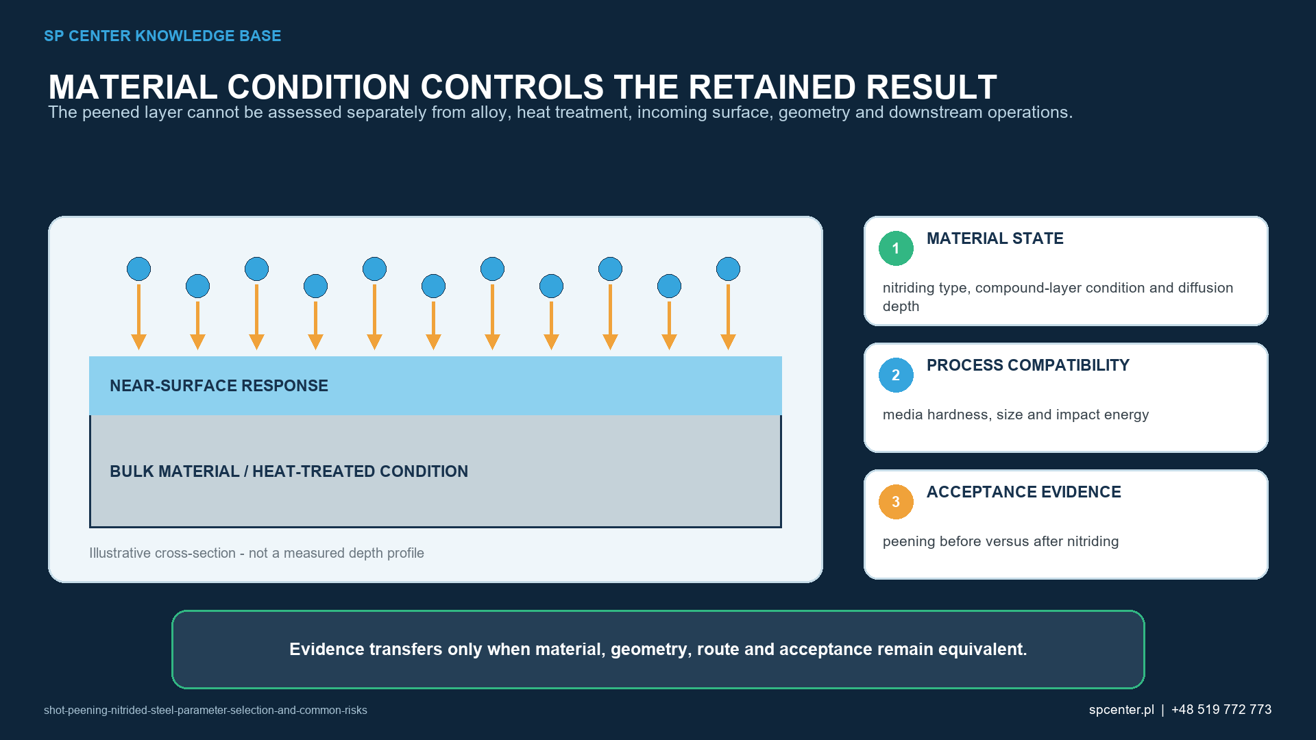
Nitriding introduces nitrogen into a suitable steel at elevated temperature. Depending on alloy and process control, the outer surface may contain a nitride-rich compound layer, commonly called the white layer because of its appearance in a prepared metallographic section. Beneath it lies a diffusion zone containing nitrogen in solid solution and alloy-nitride precipitates, followed by the core.
These regions do not have one common hardness, toughness or response to impact. Compound-layer thickness, phase constitution, porosity and continuity, together with diffusion-zone depth and core condition, must follow the applicable drawing and nitriding specification. The informal term “white layer” is not by itself an acceptance criterion.
| Surface state or route | Main concern | Controlled decision |
|---|---|---|
| Peening before nitriding | Nitriding temperature and time can relax or redistribute peening-induced residual stress and create a new surface condition | Qualify the complete thermal route; do not credit the pre-nitriding stress state without evidence |
| Peening after nitriding with compound layer retained | A hard, porous or locally brittle compound layer may crack, chip, spall or roughen under unsuitable impacts | Define compound-layer acceptance and use representative damage stop criteria |
| Peening after specified compound-layer removal | The diffusion zone and remaining case can still be damaged or over-roughened | Verify removal, remaining case depth, surface integrity and the new peening window |
| Gas-nitrided part | Nitriding potential, temperature, time and surface activation influence compound layer and diffusion zone | Use the actual controlled nitriding specification and lot evidence |
| Plasma or ion-nitrided part | Edge effects, masking boundaries and local layer development may differ from gas nitriding | Qualify actual geometry and ion-nitriding route; do not assume interchangeability |
| Nitrocarburized surface | Carbon-bearing layer chemistry and finish differ from conventional nitriding | Treat as a distinct process and apply its governing requirements |
Table 1. Nitriding route and sequence change the surface presented to the peening stream.
Why is process sequence the first engineering decision?
When peening precedes nitriding, the nitriding thermal cycle can relax or redistribute the peening-induced residual-stress field. Nitriding also develops its own case, microstructure and residual stresses. A pre-nitriding Almen result therefore cannot demonstrate the final component state.
When peening follows nitriding, impacts act directly on the compound layer or on a surface from which that layer has been removed. A continuous, porous, thin, thick or locally brittle layer can respond differently. The selected sequence must be qualified as a combined material and manufacturing route, not as two independent conforming operations.
How do gas, controlled-potential and ion nitriding differ?
Gas nitriding controlled by ammonia dissociation, automated gaseous nitriding controlled by nitriding potential and ion nitriding are distinct routes covered by different SAE material specifications. Atmosphere control, activation, temperature-time history, masking and geometry influence layer development. A process record saying only “nitrided” is insufficient for peening qualification.
Nitrocarburizing also introduces carbon and is not automatically equivalent to nitriding. Its surface phases, compound-layer condition and later finishing requirements must be evaluated under the governing process definition.
How are media and intensity selected for a nitrided case?
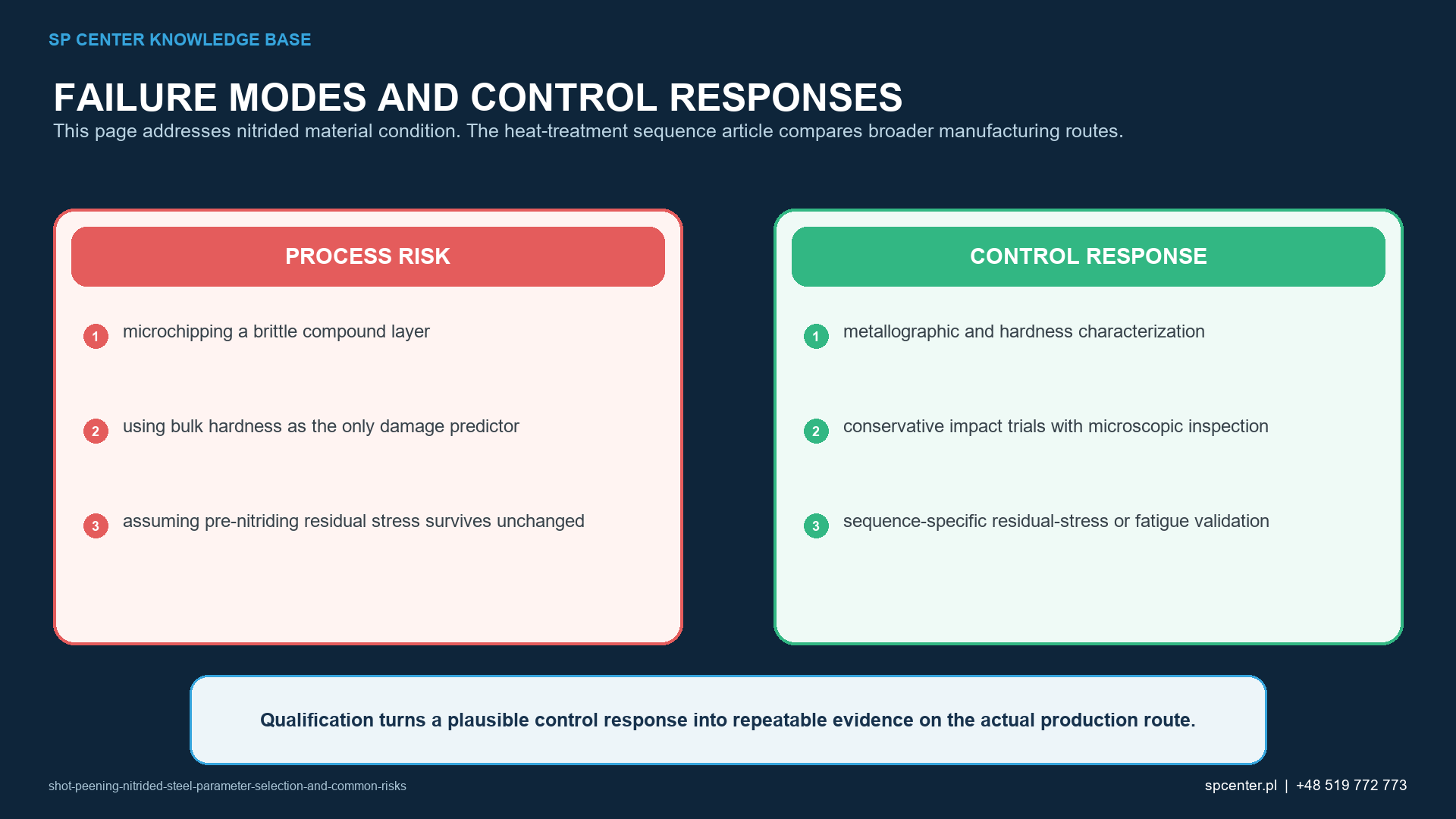
Media material, size, hardness, shape and condition interact with velocity, impact angle, media mass flow, exposure and the local layer. Media that is too soft for the intended transfer of energy may deform or break and produce an unstable stream; a harder, larger or faster particle can increase microchipping, roughness and edge damage. Neither “fine media” nor “low intensity” is an automatic safety statement.
Start from the governing peening requirement and establish a bounded window on representative nitrided material and geometry. Use stop criteria for cracks, chipping, spalling, roughness, edge rounding and dimensional change. If the nitriding lot or compound-layer condition changes, the previous window may no longer be representative.
What do the process-control results prove?
| Evidence layer | What it establishes | What it cannot prove alone |
|---|---|---|
| Material, prior heat treatment and core properties | The steel entering nitriding matches the authorized baseline | The compound layer or nitrided case is conforming |
| Nitriding record and representative metallography or hardness traverse | The specified nitriding route, layer condition and case-depth criteria are met | Peening will not microchip or roughen the actual feature |
| Media condition and machine settings | The authorized particles and equipment inputs are reproduced | Impact conditions are acceptable on every nitrided edge, root or bore |
| Almen intensity and saturation | The peening stream is verified in the approved Almen arrangement | The nitrided case is intact or has the required residual-stress profile |
| Component coverage and surface inspection | The treatment zone is covered and visible damage and texture meet defined limits | Subsurface cracks, case depth or fatigue performance is proven |
| Residual-stress depth profile and representative fatigue testing | The selected material, nitriding and peening sequence supports a defined application claim | The result transfers to another steel, layer condition, geometry or load spectrum |
Table 2. Nitriding conformance, stream verification, component acceptance and service validation must remain distinct.
SAE J442 and J443 define the Almen tools and procedures used to determine and verify peening intensity. SAE J2277 addresses coverage. A valid saturation curve verifies the stream in its approved test arrangement; it does not prove that the nitrided compound layer is crack-free or that the required case and residual-stress depth are retained.
How should coverage and surface damage be inspected?
Coverage is the proportion of the required surface carrying impact evidence when assessed by the authorized method. It is not hardness, damage detection or residual-stress measurement. Hard, dark, textured or geometrically restricted nitrided surfaces can require a qualified viewing setup, magnification or an approved indirect method correlated to the required direct assessment.
Surface acceptance may need visual or microscopic inspection, roughness measurement, dimensional checks and an appropriate customer-specified inspections outside SP Center's service scope method. The inspection method and acceptance threshold must be specified; a generic “no damage” statement is not auditable.
How is the nitrided case verified after peening?
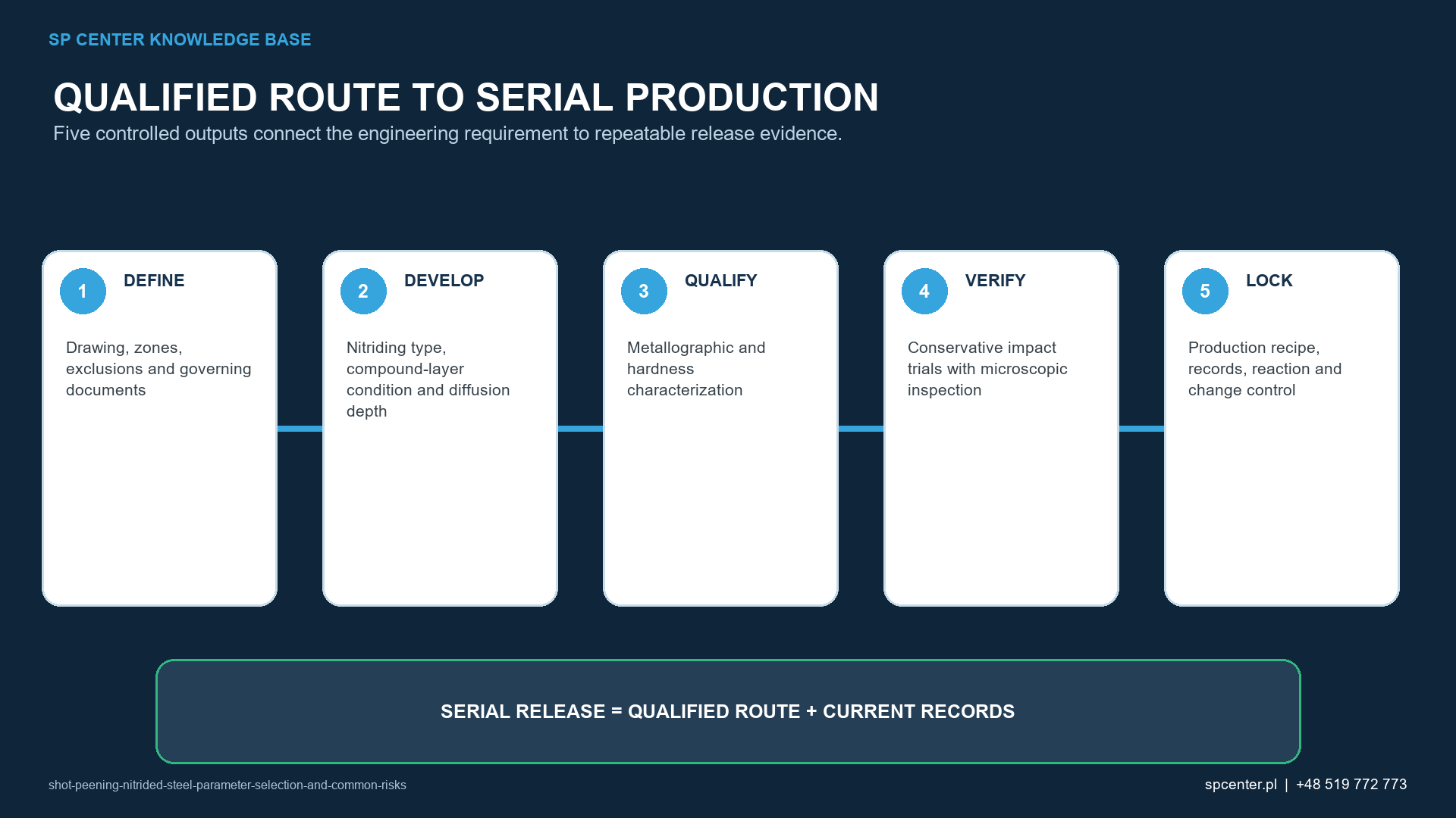
Representative metallography and a specified hardness-depth method can verify the compound layer and nitrided case produced by the heat-treatment lot. Sampling location, preparation, hardness load, case-depth definition and acceptance values must follow the governing requirement. A flat witness coupon is useful only when its material and thermal history represent the controlled part decision.
If residual-stress evidence is required, define measurement direction, location, layer-removal method, depth increments and uncertainty. The nitriding-generated stress state and the peening-induced redistribution must be interpreted together. A single surface value is not a depth profile.
What do published fatigue results mean for production?
SAE papers report fatigue behaviour for specific AISI 4340 specimens and for particular nitrided, multi-stage-peened valve springs. They demonstrate that sequence, stress concentration, layer condition and a qualified fine-media stage can materially affect performance. Their media sizes, stresses and fatigue gains are not universal production settings.
A component claim should be supported by representative geometry, material and nitriding lot, the qualified peening route and the actual load spectrum and environment. Increased coverage or an additional peening stage does not automatically improve fatigue life.
Which findings require containment?
- Steel grade, core heat treatment, nitriding route or lot differs from the qualified baseline.
- Compound-layer thickness, porosity, continuity, hardness or case depth is outside the governing limit.
- Cracking, microchipping, spalling, edge damage or unacceptable roughness is observed.
- Media identity, operating mix, intensity, coverage or equipment route is nonconforming.
- A required root, flank, bore or transition is missed or an excluded precision surface is exposed.
- Grinding, polishing, coating, repair or thermal processing changes the qualified surface sequence.
Stop processing and contain product from the last verified acceptable state. Preserve steel, heat-treatment, nitriding, media, equipment, Almen, fixture and inspection records and obtain an authorized disposition. Repeat peening or polishing is not an automatic correction.
What should the RFQ and qualification plan contain?
| Input for RFQ or qualification | Required information | Risk prevented |
|---|---|---|
| Steel and core condition | Exact grade, product form, prior heat treatment, strength or hardness range and cleanliness class where applicable | A process is transferred between different substrate responses |
| Nitriding definition | Gas, controlled-potential gas, plasma or other route; governing specification; required case depth; compound-layer requirement; hardness and microstructure limits | ‘Nitrided’ is treated as a complete surface specification |
| Manufacturing sequence | Final machining, grinding, polishing, peening, nitriding, compound-layer removal, coating and post-treatment order | Heat or material removal invalidates the intended surface state |
| Treatment map | Roots, flanks, journals, bores, threads, sharp edges, exclusion zones and transitions | The stream damages a precision surface or misses a stressed feature |
| Peening controls | Media type, size, hardness and condition, intensity range, coverage, equipment route and damage limits | A generic high-intensity or hard-media recipe is used |
| Acceptance and records | Roughness, dimensions, edge condition, cleanliness, customer-specified inspections outside SP Center's service scope, case verification, residual-stress or fatigue evidence and change authority | Stream conformance is mistaken for component or service acceptance |
Table 3. A usable request defines both the nitrided case and the peening application.
Also state part size and mass, quantity, handling and cleanliness, certificates, sampling, customer source approval and ownership of deviations and changes. If compound-layer disposition, process sequence or damage limits are missing, obtain controlled engineering clarification before processing.
Frequently asked questions
Should shot peening be performed before or after nitriding?
There is no universal sequence. Nitriding after peening can alter the peened stress state; peening after nitriding can damage the compound layer. Qualify the complete route for the actual part.
What is the compound layer?
It is the outer nitride-rich region formed by some nitriding routes, often called the white layer from its metallographic appearance. Its thickness, phase balance, porosity and acceptance depend on the requirement.
Is the diffusion zone the same as the compound layer?
No. The diffusion zone lies beneath the outer surface region and contains nitrogen in solid solution and alloy-nitride precipitates; it has different properties and acceptance criteria.
Must the compound layer always be removed before peening?
No universal rule applies. Retention, controlled removal or absence must follow the drawing, nitriding specification and qualified process sequence.
Does lower Almen intensity guarantee that a nitrided surface will not crack?
No. Media size, hardness, shape, angle, exposure, compound-layer condition, geometry and incoming defects also affect damage risk.
Can coverage be accepted from Almen intensity alone?
No. Intensity and component coverage are different controls. Coverage must be assessed on the required surface by the authorized method.
Can shot peening repair a porous or cracked compound layer?
No. A nonconforming layer requires the specified inspection and authorized disposition. Peening must not be used to conceal the condition.
What should be supplied for a feasibility review?
Provide steel grade and heat treatment, nitriding route and case requirements, compound-layer condition, drawing and zones, process sequence, peening requirement, surface limits and service loading.
Key takeaways
- Do not treat the compound layer, diffusion zone and core as one hard surface.
- Qualify peening and nitriding as one manufacturing sequence.
- Use the actual nitriding route, layer condition and case-depth requirement.
- Set a bounded media and intensity window with explicit microdamage and roughness limits.
- Separate Almen intensity and coverage from case integrity and fatigue performance.
- Use published results only within their tested material, geometry and loading scope.
Related SP Center guides
- Shot Peening Before or After Heat Treatment
- Shot Peening Carburized Steel
- Shot Hardness in Shot Peening
- Surface Roughness After Shot Peening
Technical references
1. SAE J2441_202511: Shot Peening, stabilized November 2025
2. SAE AMS2430U: Shot Peening, revised April 2018
3. SAE ARP7488: Peening Design and Process Control Guidelines, issued January 2018
4. SAE AMS2759/6D, Gaseous Nitriding of Steel Parts, Controlled by Ammonia Dissociation
5. SAE AMS2759/8B, Ion Nitriding
6. SAE AMS2759/10D, Automated Gaseous Nitriding Controlled by Nitriding Potential
7. SAE J442_202602: Tools for Peening Intensity Determination and Verification, revised February 2026
8. SAE J443_202512: Procedures for Determining and Verifying Peening Intensity, revised December 2025
9. SAE J2277_202301: Shot Peening Coverage Determination, revised January 2023
Standards and evidence note: The cited fatigue papers concern specified AISI 4340 specimens and valve-spring materials, processes and loads. They do not define a universal nitrided-steel recipe. Use complete controlled job requirements.
Author: Paweł Kmieć
Discuss a nitrided-steel peening qualification: +48 519 772 773 | [email protected]