


Understand how the field forms, describe it as a directional depth profile and validate how much of it remains after the complete manufacturing and service-relevant route
Controlled shot peening can create a near-surface field of compressive residual stress through localized plastic strain constrained by the surrounding material. The result is not one universal number. Surface stress, subsurface maximum, depth, gradient, direction, location and stability describe different aspects of the profile. Whether that profile is beneficial depends on the actual material, geometry, surface condition, manufacturing route and service loading.
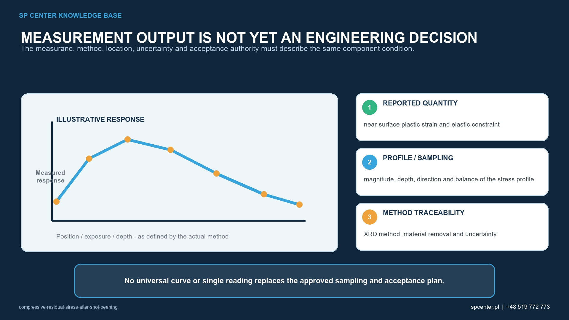
How does shot peening create compressive residual stress?
Each controlled media impact plastically deforms a small surface region. Material below and around that region responds largely elastically and restrains the permanent expansion. After the impact load has passed, the constrained layer tends to remain in compression relative to the underlying material.
Residual stress must be internally balanced across the component. A compressive near-surface region is accompanied by balancing stresses elsewhere; the exact distribution depends on geometry, section thickness and boundary conditions. It is therefore inaccurate to discuss compression without the full component and depth context.
How does residual stress change local loading?
The residual-stress tensor combines with stress generated by external loads. In a suitable application, near-surface compression can reduce the tensile portion of the local stress history at a likely surface crack-initiation site. It does not remove the external load, eliminate all tensile stress or guarantee that no crack can initiate.
Fatigue initiation and growth can involve tensile, shear and mixed-mode mechanisms. Surface defects, roughness, microstructure, notches, fretting, corrosion and load sequence still matter. Any durability credit must be validated for the relevant component and failure mechanism.
Why is a profile more useful than a single value?
| Profile descriptor | Engineering meaning | Reporting need |
|---|---|---|
| Surface or near-surface stress | Direction-specific stress evaluated in the effective sampled volume near the current surface | Location, direction, method, surface state, sign convention and uncertainty |
| Maximum compressive stress | Most compressive measured value in the resolved profile; it can occur below the surface | Value, depth, direction, measurement spacing and uncertainty |
| Depth of maximum compression | Position at which the measured profile reaches its most compressive value | Reference surface, layer-removal or depth method and depth uncertainty |
| Compressive-zone or crossover depth | Depth to the defined zero crossing or other invoked boundary of the compressive field | Definition, interpolation rule, last measured point and correction basis |
| Gradient and profile shape | Rate and pattern of stress change with depth, including possible near-surface relaxation | Sufficient depth resolution and complete plotted data |
| Direction and location | Residual stress can be anisotropic and strongly feature-dependent | Component coordinate system and drawing-linked measurement position |
| Retained profile | Stress state after a defined thermal, mechanical or manufacturing exposure | Exact exposure, sequence and comparison with the same measurement basis |
Table 1. A residual-stress result is incomplete without its location, direction, depth basis, method and uncertainty.
Two components can have similar near-surface values and different subsurface maxima or affected depths. Conversely, a more compressive number is not automatically preferable if it is associated with roughness, folds, edge damage, distortion or an unstable material state.
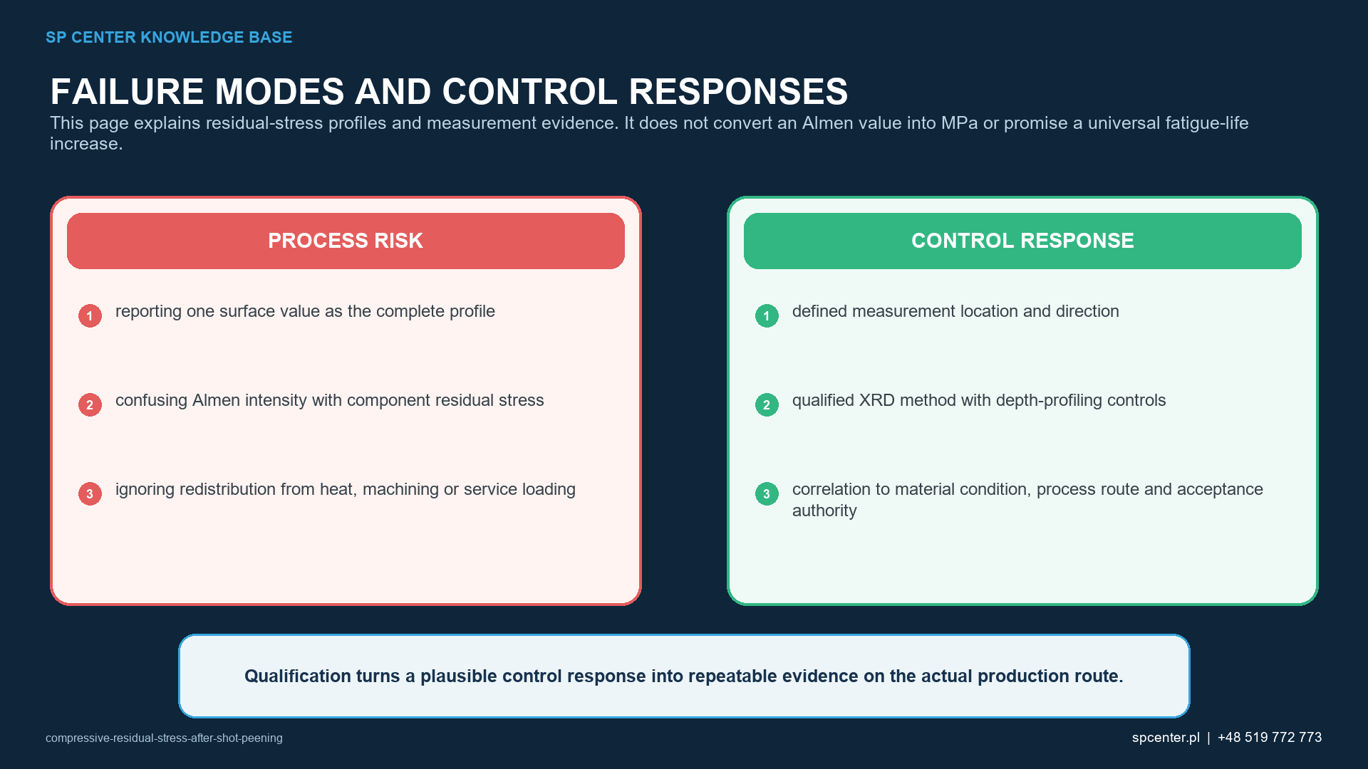
What controls the profile?
| Influence | How it can change the profile | Why no universal setting follows |
|---|---|---|
| Material and microstructure | Yield response, work hardening, phase, texture and heat-treatment state govern plastic strain and elastic constraint | Different alloys or conditions can respond differently at the same Almen intensity |
| Incoming surface and prior stress | Grinding, machining, forming, heat treatment and damage change the initial state and crack-initiation sites | The peened profile is superimposed on a component-specific baseline |
| Media | Material, size, hardness, shape and operating mix change impact momentum, contact and surface damage risk | Larger or harder media are not automatically better |
| Stream and exposure | Velocity/energy, angle, mass flow, access, overlap and time influence plastic-strain distribution | Pressure or nominal cycle time alone does not define the component profile |
| Geometry and section | Curvature, thickness, notch constraint, edge proximity and access alter impact and stress redistribution | A flat coupon may not represent a root, bore, tooth or thin wall |
| Downstream and service exposure | Heat, overload, cyclic loading and material removal can relax, redistribute or remove stress | The as-peened profile is not automatically the retained service profile |
Table 2. The component profile is the coupled result of material, incoming state, media, stream, exposure, geometry and later processing.
Do not select one “best” shot size, pressure, intensity or coverage for an alloy family. Qualify a process window for the exact component and governing requirement. When the profile itself is an acceptance feature, define measurement location, directions, depth range and comparison logic before the trial.
How are residual stresses measured?
X-ray diffraction is widely used for direction-specific near-surface residual-stress measurement in crystalline materials. A depth profile commonly requires repeated measurement after controlled layer removal, making the procedure locally destructive and potentially requiring redistribution correction. Other methods may be appropriate for different depths, geometries or materials.
Every value needs method context: material phase, reflection, coordinate system, location, direction, effective sampling, elastic constants, alignment, fit quality, uncertainty and any removal history. The dedicated XRD measurement guide explains these controls in detail.
Why can the profile change after peening?
Residual stress is not permanently fixed. Heating can promote relaxation; cyclic or dwell loading and overload can redistribute the field; creep can matter at elevated temperature; and grinding, polishing, machining or chemical removal can remove part of the affected layer. Coating and heat-treatment sequences can add further thermal or mechanical changes.
When a service or life claim depends on retained compression, evaluate the profile after the complete manufacturing route and representative thermal-mechanical exposure. An as-peened room-temperature profile cannot automatically be credited through later processing or service.
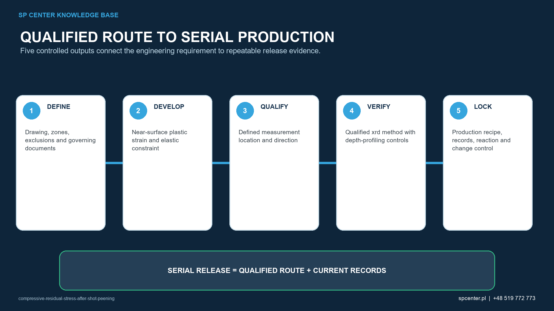
Which evidence belongs to which decision?
| Evidence | What it establishes | What it cannot establish alone |
|---|---|---|
| Almen intensity | Standardized response of the peening stream under the invoked tools and procedure | Residual-stress magnitude, direction or depth in the component |
| Coverage | Extent of accepted impact-impression coverage on the specified surface | Peening intensity, profile depth or fatigue performance |
| Surface and dimensional acceptance | The component meets invoked condition, roughness, edge, cleanliness and dimensional limits | The complete residual-stress field |
| XRD or other qualified stress measurement | Direction- and location-specific residual-stress result under the stated method | Automatic production conformity or service-life improvement |
| Representative fatigue/SCC validation | The defined material, geometry, process and service simulation support an application claim | Transfer to another route or proof that every production cycle was controlled |
Table 3. Intensity, coverage, component acceptance, residual stress and fatigue evidence are complementary but not interchangeable.
How should a residual-stress requirement be specified?
State the component and drawing revision, material and heat treatment, complete manufacturing state, treatment area, governing document and purpose of the measurement. Define coordinate system, measurement locations and directions, surface or depth profile, maximum depth, depth increments, sign convention, method, uncertainty expectations and acceptance authority.
Avoid a single requirement such as “minimum compressive stress” without location, direction and depth. Define whether the requirement applies as-peened, after finishing, after thermal exposure or after representative loading. If a coupon is allowed, its relationship to the actual part must be established.
What records support a qualified profile?
- Part/coupon identity, alloy, heat treatment, incoming surface and prior residual-stress state where relevant.
- Qualified media, intensity, coverage, fixture, motion, masking and process-window records.
- Exact measurement location, direction, coordinate system and surface condition.
- Measurement method, raw data quality, uncertainty and depth-removal/correction history.
- Surface, dimensional and defect acceptance for the same manufacturing state.
- Thermal, mechanical or service-relevant exposure applied before retained-profile measurement.
- Approved comparison, acceptance decision, deviations and traceability to the actual lot.
What are compressive residual stresses after shot peening?
They are internally balanced stresses that remain after localized impact-induced plastic strain is constrained by surrounding material. A compressive region is commonly created near the treated surface, with balancing stresses elsewhere in the component.
Is maximum compression always at the surface?
No. The most compressive measured value can occur below the surface. Surface value, depth of maximum compression and crossover depth are separate profile descriptors.
Is a deeper compressive profile always better?
No. The useful profile depends on material, geometry, expected crack origin, load spectrum, surface integrity and stability. Greater depth gained at the cost of damage, roughness or distortion can be unacceptable.
Can Almen intensity be converted into residual stress in MPa?
No universal conversion exists. Almen intensity characterizes a standardized strip response; component residual stress depends on material, geometry, surface state, media, access, exposure and measurement method.
Does 100% coverage prove the required residual-stress profile?
No. Coverage shows that the required surface was covered by impact impressions under the accepted method. It does not quantify stress magnitude, direction or depth.
Can residual stress relax after shot peening?
Yes. Thermal exposure, cyclic loading, overload, creep or dwell conditions, machining and other later operations can relax, redistribute or remove part of the profile. Stability must match the intended route and service claim.
Does compressive residual stress guarantee longer fatigue life?
No. It can beneficially modify local loading in a validated application, but fatigue also depends on surface defects, roughness, geometry, material, mean stress, load spectrum, environment and profile stability.
Must residual stress be measured on every production part?
Not universally. Measurement frequency and whether XRD is required for qualification or release follow the drawing, specification, process plan and customer requirements. It is not a routine substitute for stream and coverage controls.
Key takeaways
- Shot peening produces an internally balanced residual-stress field through plastic strain and elastic constraint.
- Describe the field by surface value, subsurface maximum, depth, gradient, direction and location.
- Maximum compression can occur below the surface; deeper or higher is not automatically better.
- Almen intensity and coverage do not quantify component residual stress.
- Heat, loading and material removal can relax, redistribute or remove the profile.
- Any fatigue or service credit requires representative validation of the retained final state.
Related SP Center guides
- XRD Residual Stress Measurement After Shot Peening
- Residual Stress Depth Profile After Shot Peening
- How Shot Peening Improves Fatigue Life
- Shot Peening Process Window
Technical sources
2. SAE ARP7488: Peening Design and Process Control Guidelines, issued January 2018
3. SAE AMS2430U: Shot Peening, revised April 2018
5. Analytical and experimental study of residual-stress profiles in shot-peened steels, 2024
Standards note: Apply the complete drawing, customer requirements and invoked specification revisions. These sources do not define one universal residual-stress profile, fatigue factor or production measurement frequency.
Author: Paweł Kmieć
Discuss a residual-stress requirement for controlled shot peening: +48 519 772 773 | [email protected]