


Review material–environment compatibility, pressure-boundary integrity and failure mechanism before qualifying feature-specific peening, inspection and release evidence
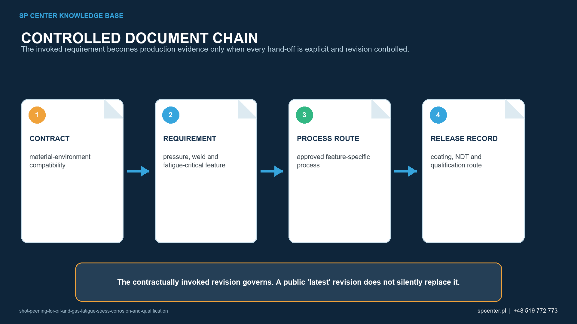
Shot peening for oil and gas components is not a generic corrosion or pressure-integrity treatment. It can be considered for selected fatigue- or environment-sensitive surfaces only after the exact material condition, service environment, pressure/weld function, defects, coatings, customer-specified inspections outside SP Center's service scope sequence and governing sector requirements are understood. Compressive residual stress is one engineering layer—not a substitute for suitable material, corrosion control or fitness-for-service decisions.
What must be known before shot peening is selected?
| Engineering input | Question before peening | Authority/evidence |
|---|---|---|
| Material and condition | What grade, product form, heat treatment, hardness and manufacturing/repair history apply? | Controlled drawing, material records and applicable design/material rules |
| Service environment | Are H₂S, chlorides, water chemistry, temperature, pressure, cyclic load or cathodic protection relevant? | Approved service assessment and material–environment qualification |
| Failure mechanism | Is the concern fatigue initiation, fretting, stress-corrosion/sulfide cracking, corrosion fatigue or another mechanism? | Design or integrity authority’s documented basis |
| Pressure boundary and defects | Are cracks, weld defects, corrosion damage or dimensional loss present? | Required customer-specified inspections outside SP Center's service scope, inspection and fitness-for-service/repair disposition before peening |
| Surface sequence | Which coating, plating, overlay, machining, cleaning or inspection steps precede/follow peening? | Authorised manufacturing or repair sequence and acceptance criteria |
Table 1. The peening decision follows material, environment, failure mechanism and pressure-boundary review.
ISO 15156-1:2020 provides general principles for selecting and qualifying metallic materials in H₂S-containing oil-and-gas production environments and supplements rather than replaces applicable design rules. It does not qualify a shot peening recipe. A process must never be used to imply sour-service suitability where the material, hardness or environment has not been accepted through the governing route.
Why can shot peening not repair a pressure-boundary defect?
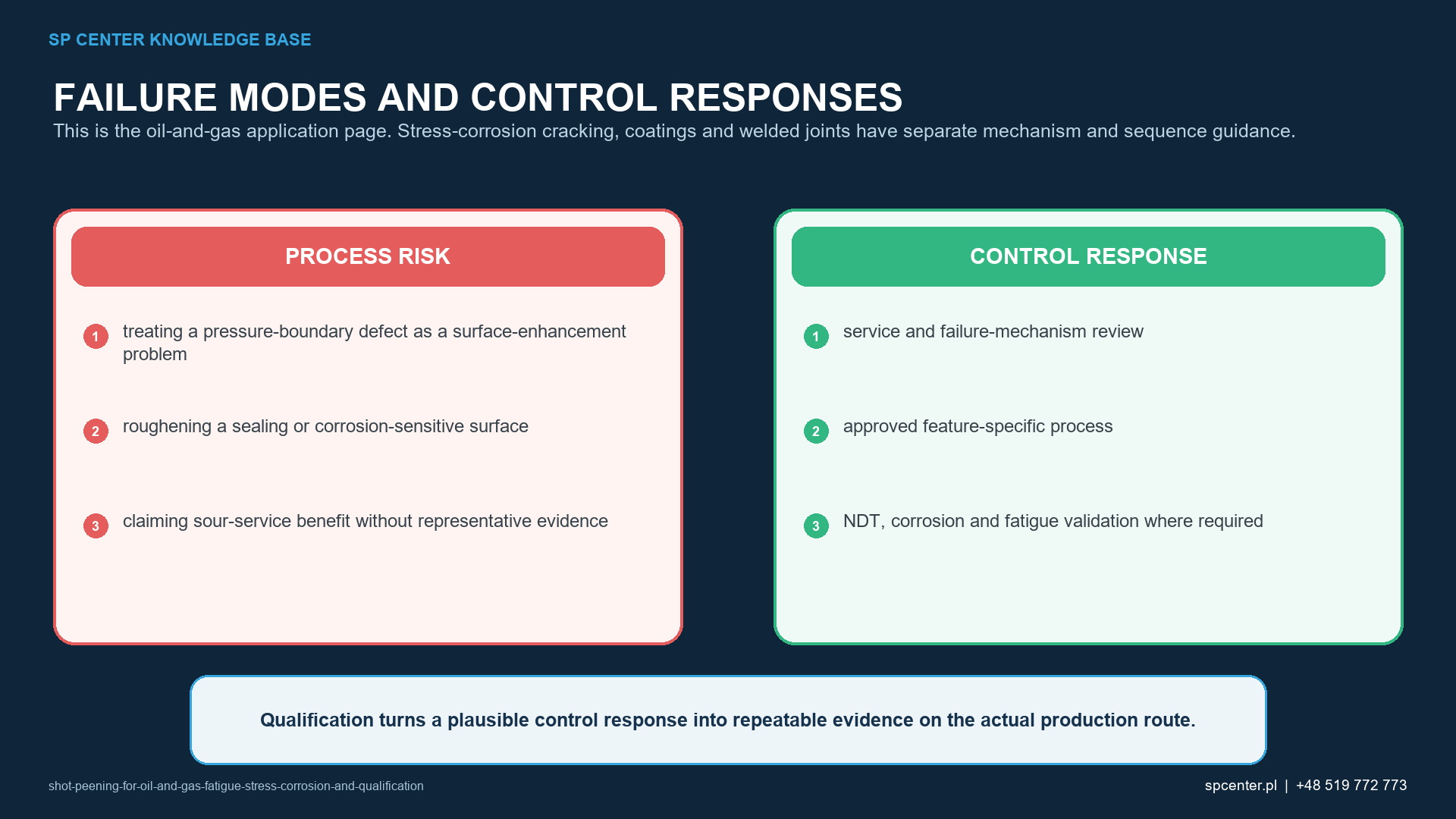
Shot peening plastically modifies a near-surface layer; it does not remove a crack, weld defect, corrosion pit network or wall loss. Treating a defect can alter surface appearance and complicate later interpretation without restoring pressure integrity. Required customer-specified inspections outside SP Center's service scope, dimensional inspection and engineering disposition therefore precede any surface-enhancement decision.
For in-service or repair components, contamination, corrosion products, service history, remaining dimensions and prior repairs make the incoming condition fundamentally different from a new component. A production recipe cannot be applied without an authorised repair/fitness route.
Which features need their own treatment decision?
| Feature | Primary risk | Shot peening control question |
|---|---|---|
| Pressure-retaining body or bore | Defect masking, dimensional/roughness change, retained media | Is treatment permitted, inspectable and compatible with pressure-boundary acceptance? |
| Weld toe or HAZ-adjacent surface | Existing discontinuity, variable metallurgy, geometry and residual stress | Has the weld condition been accepted and a weld-specific route qualified? |
| Thread root or connection | Access, galling/sealing function, profile and media entrapment | Are treatment zone, masking, local coverage, dimensions and cleaning defined? |
| Sealing face or coating interface | Roughness, leakage, adhesion or corrosion-barrier damage | Should the surface be treated, protected or excluded, and when in the sequence? |
| Corroded or in-service surface | Unknown damage, contamination and remaining wall/fitness | Has condition been evaluated and an authorised repair/manufacturing route established first? |
Table 2. Pressure, sealing, weld and connection features have different functional and inspection risks.
Masking or exclusion is not assumed universally; it must come from the drawing, specification, approved risk assessment or technical clarification. A sealing face may require protection, while a qualified weld-toe route may intentionally treat a fatigue-critical transition. The function and acceptance criteria decide.
How are fatigue and environment-assisted cracking claims separated?
A compressive residual-stress field can reduce the effective tensile driving condition near the surface, but the actual profile depends on material, hardness, media, intensity, coverage, exposure, geometry, impact angle and initial stress. Relaxation can depend on temperature, loading and service history. No universal benefit can be assigned from the process name.
Fatigue validation must represent the material, surface, geometry, loading and environment relevant to the claim. ASTM E466-21 addresses axial constant-amplitude fatigue tests in air at room temperature; results are suitable for design only when service conditions are realistically represented or explicitly accounted for. It is therefore not, by itself, a sour-service or full-component qualification.
Which evidence layers are required?
| Evidence | What it establishes | What it cannot establish alone |
|---|---|---|
| Almen intensity | Standardised response of the defined shot stream/setup | Pressure integrity, material–environment compatibility, coverage or residual-stress profile |
| Coverage | Extent of impact evidence on the required component surface | Correct intensity, defect freedom, acceptable roughness or sour-service performance |
| Surface/dimensional acceptance | Compliance with invoked roughness, damage, masking, profile and dimensional criteria | Subsurface stress state, fatigue life or environmental cracking resistance |
| customer-specified inspections outside SP Center's service scope result | Indications/discontinuities found by the stated method, stage and acceptance criteria | Shot peening process capability or universal fitness for service |
| Residual-stress/corrosion/fatigue validation | Response under the stated material, environment, geometry and test conditions | Transferability beyond the validated case |
Table 3. Process verification, defect inspection and service-performance evidence answer different questions.
How do coating and customer-specified inspections outside SP Center's service scope sequences affect qualification?
Peening before or after coating, overlay, plating, machining or customer-specified inspections outside SP Center's service scope can change access, surface texture, contamination, adhesion and detectability. The approved sequence must define incoming preparation, any pre-peening inspection, masking, peening, coverage inspection, cleaning/media removal, post-peening inspection and coating or assembly.
Do not assume a post-peening customer-specified inspections outside SP Center's service scope method has the same capability on a modified surface. Method, surface condition, sensitivity, acceptance and sequence must follow the approved inspection plan.
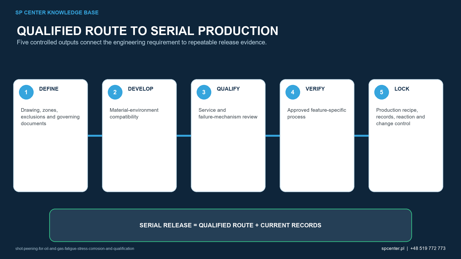
How is an oil-and-gas peening route qualified?
| Qualification stage | Required output | Release boundary |
|---|---|---|
| Contract and service review | Drawing/specification hierarchy, material/environment, feature function and design authority | No processing while requirements or service mechanism remain unresolved |
| Incoming-condition acceptance | Required customer-specified inspections outside SP Center's service scope, defect/corrosion disposition, dimensions, cleanliness and prior-process status | Peening does not repair cracks, weld defects or wall loss |
| Process development | Approved media, equipment, intensity, geometry, masking, motion, coverage and exposure | No universal oil-and-gas recipe or sour-service claim |
| Component qualification | Surface, dimensions, coverage and any required residual-stress, corrosion or fatigue evidence | Standardised Almen response is not complete component validation |
| Production control | Released recipe, records, inspection, media removal, maintenance, alarms and reaction plan | Alarm-free cycle does not prove unmonitored component conditions |
| Change/rework control | Review of material, environment, geometry, welding, coating, media, equipment, program and inspection changes | No automatic re-peening after an excursion or service damage |
Table 4. Qualification links the standardised peening stream to feature-specific component and service evidence.
Reprocessing is not an automatic correction. Another cycle changes cumulative exposure and may affect roughness, dimensions, coating sequence or surface integrity. Affected product is contained and evaluated through the authorised engineering/quality route before any repeat treatment.
Can shot peening improve fatigue resistance in oil and gas components?
It may support fatigue performance when the specified mechanism, material, geometry, surface and loading case have a qualified basis. Improvement is not proven by Almen intensity or coverage alone.
Does shot peening make a material suitable for sour service?
No. Material selection and qualification for H₂S-containing environments follow the applicable design/material requirements, such as the invoked ISO 15156 route. Shot peening does not make a nonconforming material or hardness condition compliant.
Can shot peening prevent stress-corrosion cracking?
Not universally. Compressive residual stress can be relevant in some qualified material–environment combinations, but alloy, hardness, environment, surface, tensile loads and other cracking mechanisms still control performance.
Can a cracked or corroded pressure-boundary component be repaired by shot peening?
No. Cracks, weld defects, corrosion damage and wall loss require detection, engineering assessment and authorised repair or fitness-for-service disposition before any surface-enhancement process.
Should customer-specified inspections outside SP Center's service scope be performed before or after shot peening?
The governing manufacturing/repair plan defines the sequence. Required pre-peening inspection must not be skipped, and any post-peening examination must use a qualified method compatible with the changed surface.
Can weld toes be shot peened?
Potentially, but the weld must first meet its acceptance requirements. Weld profile, HAZ/base material, access, media, intensity, coverage, surface condition and performance evidence require a weld-specific qualified route.
Can shot blasting replace shot peening?
Not automatically. Shot blasting commonly cleans or prepares a surface; controlled shot peening requires specified media, Almen intensity, coverage, exposure and traceability. Substitution needs design and contractual authority.
What should an RFQ include?
Provide drawing/revision, material/heat treatment/hardness, new or service condition, environment and temperature, pressure/weld/seal features, prior and later processes, customer-specified inspections outside SP Center's service scope, zones, specifications, intensity, coverage, surface/dimensional limits, quantities and records.
Key takeaways
- Establish material, hardness, service environment and failure mechanism before selecting shot peening.
- Do not use peening to repair cracks, weld defects, corrosion damage or pressure-boundary wall loss.
- Separate fatigue, corrosion, environment-assisted cracking and pressure-integrity claims.
- Give welds, threads, seals, bores, coatings and in-service surfaces feature-specific decisions.
- Keep Almen intensity, coverage, customer-specified inspections outside SP Center's service scope and component/service validation distinct.
- Qualify coating, cleaning and inspection sequence with the actual surface condition.
- Control relevant changes and rework through the authorised route.
Related SP Center guides
Technical sources
1. SAE J2441_202511: Shot Peening, stabilized November 2025
2. SAE ARP7488: Peening Design and Process Control Guidelines, issued January 2018
3. SAE J443_202512: Procedures for Determining and Verifying Peening Intensity, revised December 2025
4. SAE J2277_202301: Shot Peening Coverage Determination, revised January 2023
Standards note: The complete contract, design/material rules, drawing, repair route and customer flow-down control. ISO 15156 is under revision; use the published revision and amendments contractually invoked for the project. This guide creates no sour-service, pressure-integrity or fatigue qualification.
Author: Paweł Kmieć
Discuss oil-and-gas shot peening feasibility and qualification: +48 519 772 773 | [email protected]