


Engineering objectives, fatigue-critical features, material conditions and industrial applications of controlled shot peening
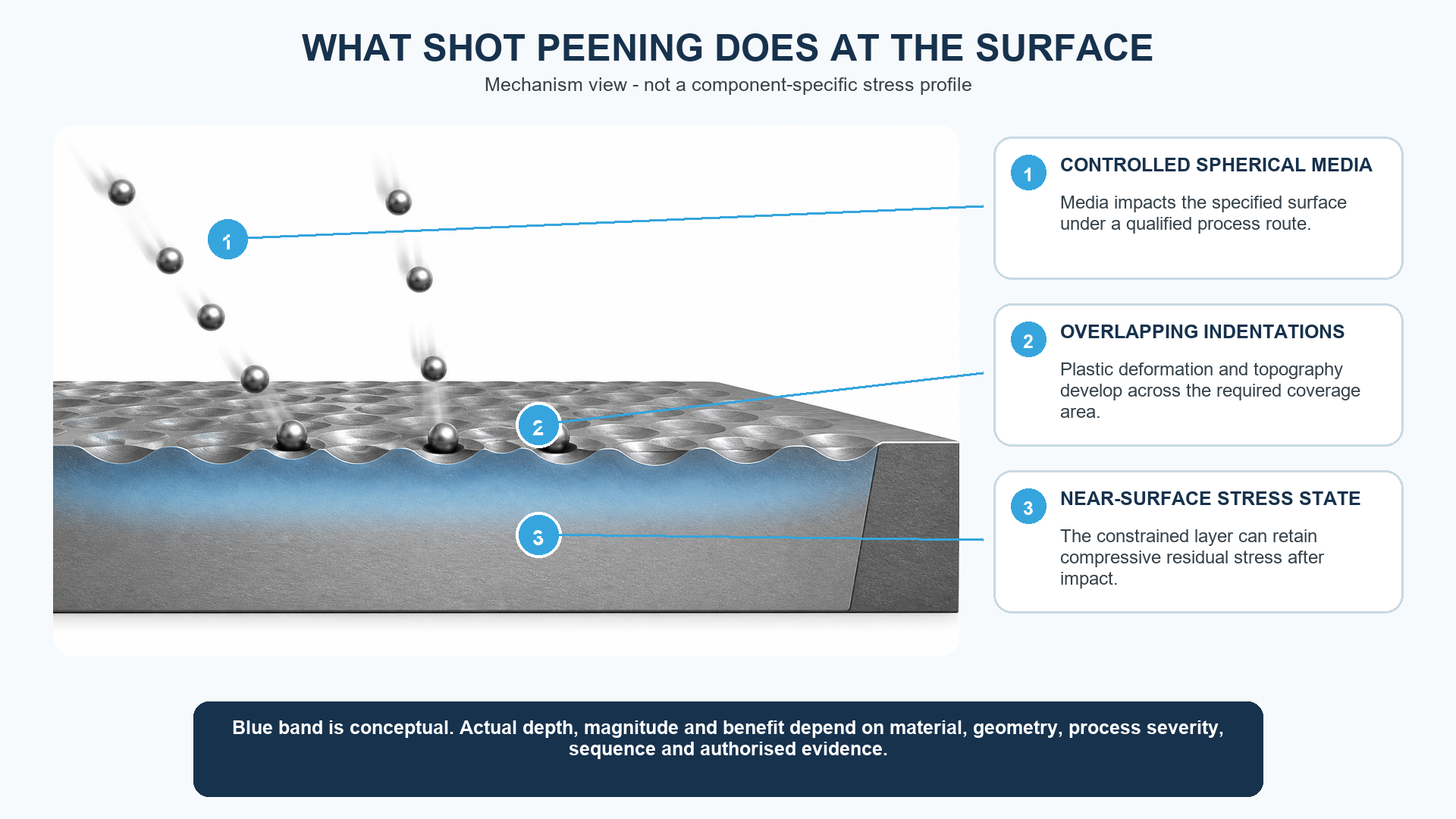
Shot peening is used to create a controlled near-surface condition on metal components, most often to support fatigue or crack resistance at highly stressed surfaces. Repeated impacts can produce compressive residual stress, cold work and a changed surface topography. The process is applied to gears, springs, shafts, holes, fillets, fasteners and other critical features in several industries—but only under a route qualified for the exact material, geometry, requirement and service objective.
What engineering objectives can shot peening support?
| Engineering objective | How shot peening may help | Required boundary |
|---|---|---|
| Fatigue resistance | A suitable compressive residual-stress state can reduce effective tensile driving force near the surface | Benefit depends on material, geometry, surface, load spectrum, environment and stress stability |
| Resistance to surface-crack initiation | Treatment can place compression and cold work at highly stressed roots, fillets or holes | Existing cracks, grinding burn or unacceptable damage must not be concealed |
| Resistance to stress-corrosion cracking | Compression can reduce tensile surface stress relevant to some material–environment systems | Applicability requires the correct alloy, environment, process and validation basis |
| Fretting-fatigue support | A treated near-surface state may improve tolerance to cyclic contact damage in qualified applications | Contact pressure, slip, roughness, debris, coating and lubrication remain decisive |
| Restoration after defined material removal | An approved route may re-establish a required treated layer after authorized machining or blending | Repair authority, remaining geometry, damage removal and requalification must be explicit |
| Distortion management in special routes | Controlled and balanced peening can influence form in an engineered peen-forming application | Peen forming is a distinct development objective and not a routine consequence of shot peening |
Table 1. Shot peening is selected against a defined engineering objective, not a generic promise of stronger metal.
The most common objective is to place a suitable compressive residual-stress field where tensile service stress and surface condition make fatigue initiation likely. The same treatment also changes roughness and local material state. Those changes must remain acceptable for dimensions, contact, sealing, coating, friction and inspection.
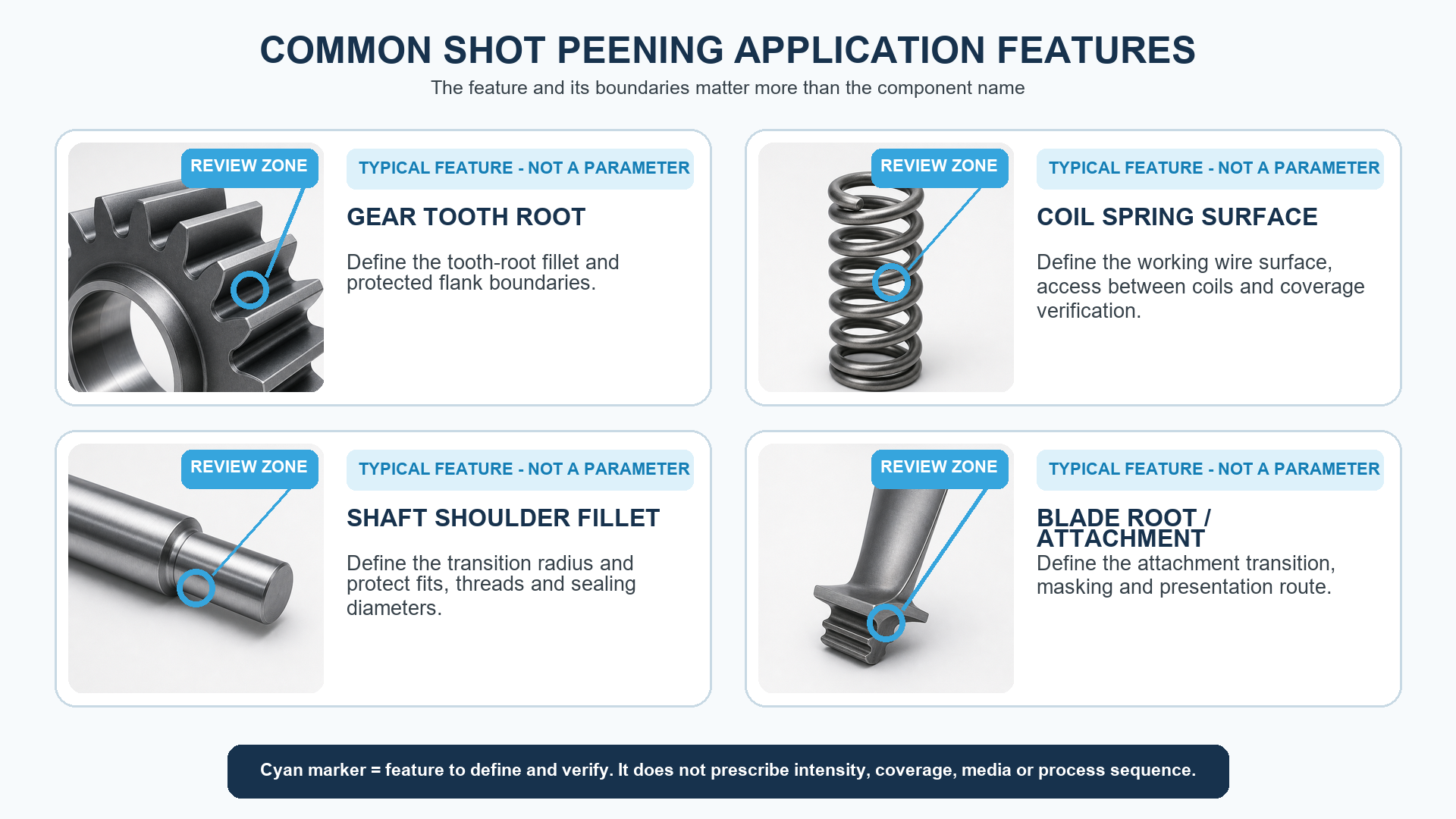
Which component features are commonly treated?
| Component feature | Why it is considered | Main process-control challenge |
|---|---|---|
| Fillet or radius | High local stress and common fatigue origin | Angle, rebound, shadowing, holder or nozzle representation and local coverage |
| Gear or spline root | Cyclic bending and contact-related stress concentration | Root access, protected flanks, media removal and representative inspection |
| Hole or bore | Stress concentration and possible crack initiation at entry, exit or internal wall | Lance or nozzle access, stream change, motion, retained media and boundary control |
| Spring or torsion element | High-cycle alternating stress near the surface | Material condition, complete exposure, distortion, surface damage and stable process window |
| Shaft, axle or crank transition | Rotating bending and local geometry changes | Circumferential uniformity, masking, handling and traceable configuration |
| Thin wall, edge or precision fit | May be fatigue-critical but sensitive to impact | Distortion, edge breakdown, roughness, dimensional change and protection |
Table 2. High-value treatment targets are often the most difficult areas to reach and inspect.
A component should not be specified only as “shot peened.” The drawing or controlled process definition needs the exact treatment boundary, exclusions, transitions and critical zones. Access to a visible outer surface does not prove access to a recessed root or internal bore. Coverage and any indirect inspection method must represent the actual geometry.
Which materials are used with shot peening?
| Material or condition | Possible application context | Important qualification questions |
|---|---|---|
| Carbon and alloy steels | Shafts, gears, springs, fasteners and structural features | Heat treatment, hardness, incoming grinding, media hardness and distortion |
| Carburized or induction-hardened steels | Gear and wear features with a hard case | Case depth, surface condition, retained austenite, microdamage and allowable impact severity |
| Nitrided steels | Hard diffusion layers on fatigue- or wear-critical parts | Compound layer, brittle response, prior finish, intensity and media compatibility |
| Stainless steels | Corrosion-sensitive springs, shafts, fasteners and structures | Contamination control, exact grade, strength condition and environment |
| Aluminum alloys | Aerospace, motorsport and industrial structures and rotating parts | Alloy and temper, thin sections, roughness, distortion and ferrous contamination |
| Titanium and nickel alloys | Highly loaded aerospace, energy and industrial components | Media restrictions, surface damage, contamination, temperature and customer-specific qualification |
Table 3. Material family is only the starting point for a qualified application.
The same alloy name can cover different product forms, heat treatments, hardness levels and incoming surfaces. Case-hardened and nitrided components require particular attention to brittle or compound layers and prior grinding. Nonferrous alloys may impose contamination and surface-damage limits that exclude media or equipment acceptable for a steel route.
Where is shot peening used in industry?
| Sector context | Representative component families | What must be confirmed |
|---|---|---|
| Aerospace | Landing-gear, engine, transmission, spring, fastener and structural features | Exact specification, approved source, Nadcap or customer scope when invoked, part qualification and traceability |
| Automotive and heavy vehicle | Gears, springs, shafts, connecting rods, crankshafts and driveline parts | Drawing route, material condition, serial capacity, cleanliness and customer quality evidence |
| Energy and power generation | Turbomachinery, shafts, gears, springs and highly loaded fasteners | Service temperature, corrosion environment, repair authority and part-level validation |
| Railway | Springs, axles, gears, shafts and safety-relevant mechanical parts | Applicable customer specification, material and heat treatment, inspection and change control |
| Motorsport | Gears, shafts, springs, connecting rods and lightweight highly stressed parts | Traceable configuration, short development loop, surface condition and realistic load validation |
| General industrial machinery | Gears, springs, tools, shafts, couplings and fatigue-critical details | Actual failure mode, value of treatment, access, acceptance and commercial batch route |
Table 4. Sector labels describe context; the contract and component define the actual route.
Aerospace work can invoke customer-source approval, Nadcap accreditation at the exact processing site, part qualification and extensive traceability. These are separate controls: Nadcap is not product certification and is required only when the contract or customer programme invokes it. Other industries can impose equally demanding component and quality requirements under different systems.
What is the difference between shot peening and shot blasting?
Shot peening has a controlled surface-engineering purpose and normally requires defined Almen intensity, coverage, media and process evidence. Shot blasting is commonly used for cleaning, scale or coating removal and surface preparation. Equipment or media may look similar, but purpose, process window, verification and acceptance differ.
A cleaning cycle must not be presented as qualified shot peening without the required evidence. Conversely, shot peening should not be expected to remove heavy corrosion, scale or coating unless a separate authorized operation is defined. When both processes are used on one part, their sequence, equipment cleanliness and acceptance criteria must remain distinct.
How does shot peening support fatigue-critical parts?
Fatigue cracks often start where local tensile stress, stress concentration and surface discontinuities interact. A suitable compressive residual-stress field can reduce the effective tensile condition near the surface and delay initiation or early propagation. Benefit depends on the treated depth remaining relevant and stable under service loading, temperature and environment.
Almen intensity does not measure component residual stress or life. Coverage does not prove fatigue performance. Where design credit is important, qualification may require XRD residual-stress characterization, roughness, dimensions, metallography, fatigue testing or other component evidence in addition to routine process controls.
Can shot peening support stress-corrosion or fretting applications?
It can be considered when surface tensile stress contributes to the relevant mechanism, but suitability is system-specific. Stress-corrosion cracking depends on alloy, microstructure, environment, tensile condition and time. Fretting depends on contact pressure, slip amplitude, debris, roughness, lubrication, coating and load. A generic process statement cannot substitute for material- and service-specific validation.
When should shot peening not be selected?
- The engineering objective, failure mechanism or treatment boundary is undefined.
- The component contains cracks, grinding burn, unacceptable corrosion or other damage without authorized disposition.
- The critical surface cannot be reached, protected or inspected by a qualified route.
- Roughness, distortion, contamination or dimensional change would be unacceptable.
- A later operation will remove or relax the treated layer without design approval.
- The requested media, intensity or exposure conflicts with the material or governing specification.
- The process is expected to compensate for an unsuitable design, material condition or manufacturing defect.
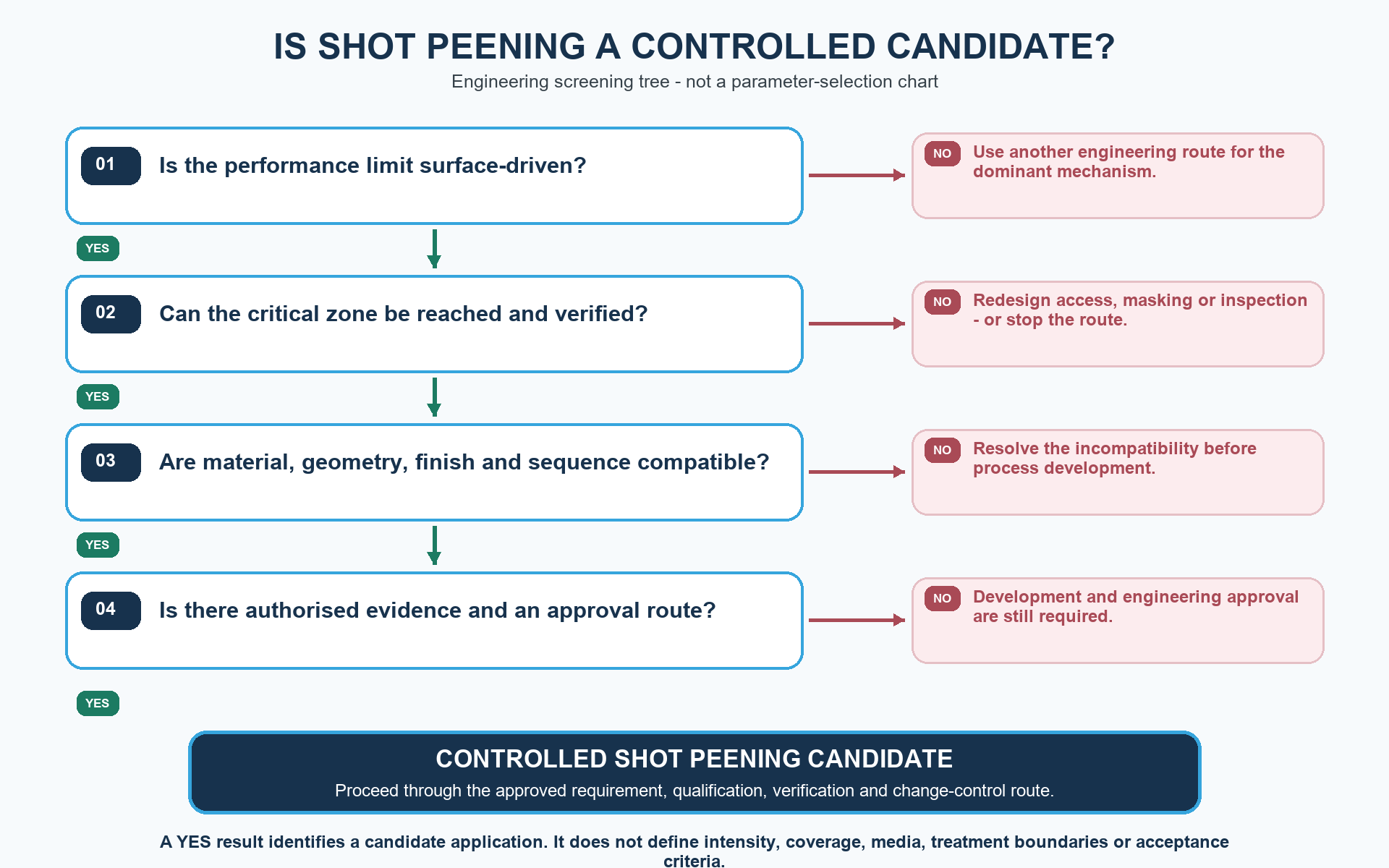
How is an application qualified?
| Decision step | Question | Required output |
|---|---|---|
| 1. Define the objective | Which surface-related failure mechanism or design requirement is being addressed? | Authorized technical objective and treated feature |
| 2. Confirm suitability | Are material, heat treatment, incoming surface, geometry and sequence compatible? | Feasibility and documented exclusions or open points |
| 3. Define the process | Which media, Almen range, coverage, equipment, motion, masking and monitoring apply? | Controlled process plan within the governing requirements |
| 4. Qualify evidence | How are intensity, coverage, surface integrity and any component performance demonstrated? | Accepted qualification basis and reaction plan |
| 5. Release production | Can the approved route be repeated with full traceability? | Work instruction, records, inspection and release authority |
| 6. Control change | Which changes require notification, approval or requalification? | Defined configuration and change-control route |
Table 5. A qualified application links design intent to controlled production and change management.
Keep three evidence layers separate. Almen and media records verify the peening stream. Coverage and surface inspection accept the actual treated area. Residual stress, fatigue, SCC, distortion or functional tests validate the component only when the design or qualification basis requires them.
What should an RFQ include?
Provide the current drawing and revision, material and product form, heat treatment and hardness, incoming surface, marked treatment and exclusion zones, design objective or service concern, complete Almen range and strip designation, coverage or exposure, permitted media, masking and cleaning, dimensions and mass, downstream operations, quantities, qualification evidence, batch records, packaging and target milestones.
Frequently asked questions
What is shot peening mainly used for?
It is mainly used to create a controlled near-surface state—commonly including compressive residual stress—on fatigue- or crack-sensitive metal features. The exact objective and acceptance basis must be defined for the component.
Which components are commonly shot peened?
Examples include gears, splines, springs, shafts, axles, crankshafts, connecting rods, fasteners, holes, bores, fillets and other highly stressed features. The family name alone does not establish suitability.
Which metals can be shot peened?
Many steels, aluminum alloys, titanium alloys, nickel alloys and some other metals can be processed under qualified routes. Exact alloy, heat treatment, hardness, case, coating and contamination limits determine suitability.
Is shot peening used to clean rust or scale?
That is normally the purpose of shot blasting or another cleaning process. Shot peening has a controlled mechanical surface-engineering objective and must not be treated as interchangeable with cleaning simply because impact media are used.
Can shot peening repair a cracked part?
No. It does not repair cracks, grinding burn, corrosion pits beyond acceptance or an unsuitable base condition. Any repair or re-peening route requires authorized engineering disposition and a defined qualification basis.
Is shot peening only used in aerospace?
No. It is used in aerospace, automotive, railway, energy, motorsport and general industrial applications. Approval, process control and validation requirements vary by customer, component and criticality.
Does every shot-peened part require fatigue testing?
No. Fatigue testing is performed when design, customer, qualification or risk requirements invoke it. Routine production normally relies on the approved process and acceptance records, with part-level testing only as required.
How do I know whether my component is suitable?
Provide the drawing, material and condition, treatment zones, failure objective, load or service context, process specifications, dimensions, surface condition and downstream sequence. A feasibility review can then identify access, damage, distortion, qualification and evidence needs.
Key takeaways
- Shot peening supports a defined surface-related engineering objective, most often fatigue resistance.
- Gears, springs, shafts, holes, fillets and fasteners are common applications, not automatic candidates.
- Exact material condition, geometry, surface and manufacturing sequence control suitability.
- Shot peening and shot blasting have different purposes and acceptance evidence.
- Almen, coverage, surface acceptance and component validation answer separate questions.
- No process can repair cracks or guarantee a universal life increase.
Related SP Center guides
- What Is Shot Peening?
- What Does Shot Peening Do to a Metal Surface?
- Shot Peening of Steel Components
- Aluminum Shot Peening
Technical references
1. SAE AMS2430U: Shot Peening, revised April 2018
2. SAE ARP7488: Peening Design and Process Control Guidelines, issued January 2018
3. SAE J442_202602: Tools for Peening Intensity Determination and Verification, revised February 2026
4. SAE J443_202512: Procedures for Determining and Verifying Peening Intensity, revised December 2025
5. SAE J2277_202301: Shot Peening Coverage Determination, revised January 2023
Standards note: The complete revisions and customer-specific requirements invoked by the contract govern.
Author: Paweł Kmieć
Discuss a component application: +48 519 772 773 | [email protected]