


Control critical fillets, shoulders, splines, keyways and holes while protecting precision seats and keeping fatigue claims tied to qualified evidence
Shot peening of shafts and axles is used on drawing-defined surface zones where fatigue cracks may initiate under rotating bending, torsion, axial load or a combined load state. The process can create beneficial compressive residual stress and may delay surface crack initiation in a qualified configuration. It does not repair existing cracks, replace correct sizing or heat treatment, or prove service life from Almen intensity alone.
How do shafts, axles and their loads differ?
A shaft commonly transmits torque; an axle commonly supports rotating parts and may be stationary or rotating. Industrial terminology is not perfectly uniform, so the part function and controlled drawing are more reliable than the name. The technical review should identify rotating bending, torsion, axial or combined loading, the expected initiation zone and any contact or fretting condition.
Surface and near-surface fatigue risk depends on stress concentration, size, material and heat treatment, finish, decarburization, grinding damage, corrosion, fretting and residual stress. Shot peening addresses only part of this system. A different internal defect or an untreated feature can still govern failure.
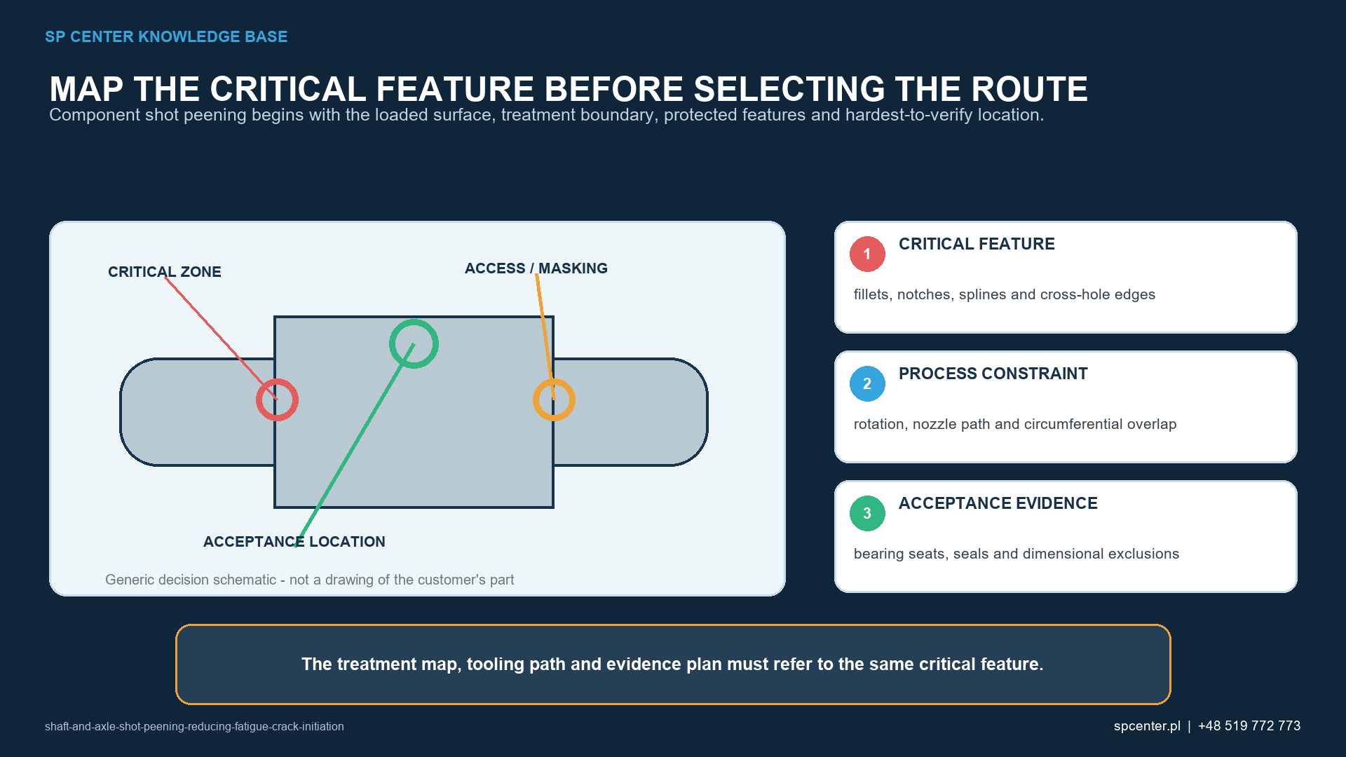
Which features require a treatment and exclusion map?
| Feature or condition | Process concern | Required engineering decision |
|---|---|---|
| Fillet or shoulder | Stress concentration and possible stream shadowing at the root | Define the actual radius, treatment boundary, stream direction and coverage method |
| Spline or keyway | Roots and side walls may receive different exposure from the outer diameter | Qualify access and inspection at the critical root rather than the easy cylindrical surface |
| Cross-hole or oil-hole edge | Edge damage, shadowing and retained media are possible | Define edge condition, permissible treatment, cleaning and inspection |
| Thread | Profile, flank and root response can affect function | Treat, exclude or mask only as required by controlled design data |
| Bearing, seal or fit seat | Roughness, diameter and contact function can be altered | State treatment or exclusion, protection method and post-process acceptance |
| Press-fit or fretting zone | Local fatigue and surface interaction may govern | Link the peening route to the assembly condition and design validation |
Table 1. The critical feature, not the most convenient cylindrical surface, determines the qualification challenge.
The drawing should distinguish treatment zones, exclusion zones and transition boundaries. Masking or protection is not automatically mandatory everywhere; it becomes a controlled requirement when invoked by the drawing, specification, customer requirement, approved risk assessment or formal engineering clarification.
Existing cracks, laps, grinding burn, excessive decarburization, corrosion damage or other rejectable conditions must be detected and dispositioned before peening where the manufacturing route requires it. Peening cannot convert an unacceptable defect into an acceptable surface.
How are rotation, access and stream overlap controlled?
A nominally simple shaft can contain difficult roots, side walls, oil holes and shoulders. Rotation speed, traverse speed or index step, nozzle or wheel direction, stand-off distance, angle, footprint and overlap must be qualified as one motion system. A stable machine setting does not prove that the critical root receives the specified coverage.
Runout, eccentricity, fixture location, clamping force and part deflection can change stand-off and incidence around the circumference. Tooling must locate the correct revision without bending the part or hiding the target zone. For holes and recesses, the route must address shadowing, media escape, cleaning and inspection access.
Where does shot peening belong in the manufacturing sequence?
The approved route should place machining, grinding, heat treatment, customer-specified inspections outside SP Center's service scope, straightening, peening, cleaning, coating or plating and assembly in a controlled order. Grinding or other material removal after peening can remove the compressive layer. Thermal exposure can relax residual stress. Straightening can change stress and runout. The effects and any renewed acceptance must be addressed before changing the sequence.
Precision journals, seal tracks, fits, threads and bores need explicit disposition. If they are excluded, the protection and boundary must be repeatable. If they are treated, surface finish, diameter, profile, runout and cleanliness limits should be stated.
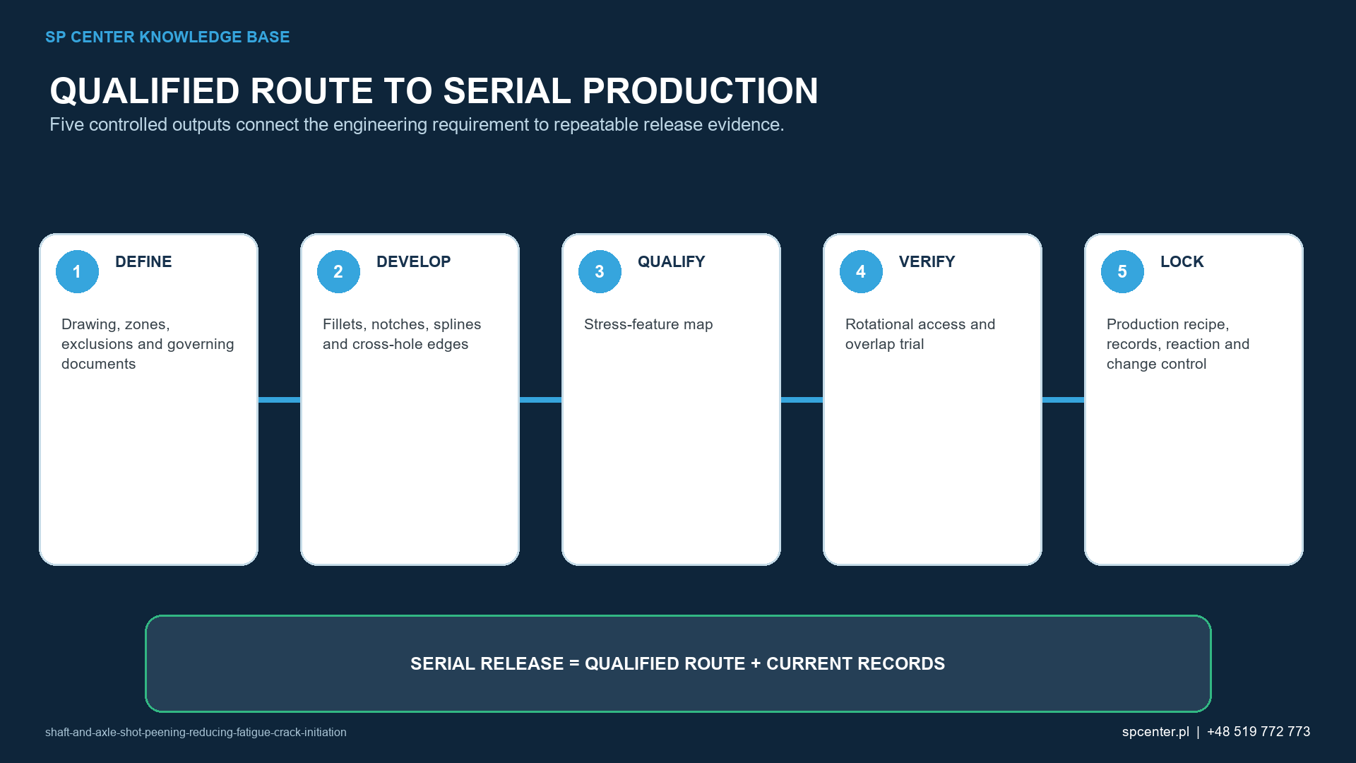
How is the process qualified for the real component?
Qualification begins with the controlled material and heat-treatment condition, incoming surface and representative geometry. It should use production equipment, media, tooling, motion and the worst credible access location. Intensity is established through the applicable Almen system and a valid saturation curve at defined verification positions; component coverage is then demonstrated separately on the required zones.
Acceptance may also include roughness, diameter, runout, straightness, cleanliness, hardness, damage or customer-specified inspections outside SP Center's service scope when invoked. Residual-stress or fatigue testing is appropriate when the design claim depends on those outputs. The plan should define alarms, reaction limits, records and changes that trigger technical review or requalification.
| Evidence layer | What it demonstrates | What it does not prove alone |
|---|---|---|
| Almen intensity and saturation | The peening stream at defined representative verification positions | Coverage of every shaft feature or fatigue improvement |
| Component coverage | Impact evidence on the specified and accessible component zone | Residual-stress depth, dimensions or absence of prior defects |
| Surface and dimensional checks | Specified roughness, diameter, runout, cleanliness and damage limits | Compressive residual stress or service life |
| Residual-stress measurement | A defined stress component at stated locations and depths | Coverage, every direction or universal fatigue performance |
| Representative fatigue test | Performance of the qualified specimen or component configuration | Automatic transfer to another material, geometry or load spectrum |
Table 2. Evidence layers are complementary and must not be substituted for one another.
Which failure modes require containment?
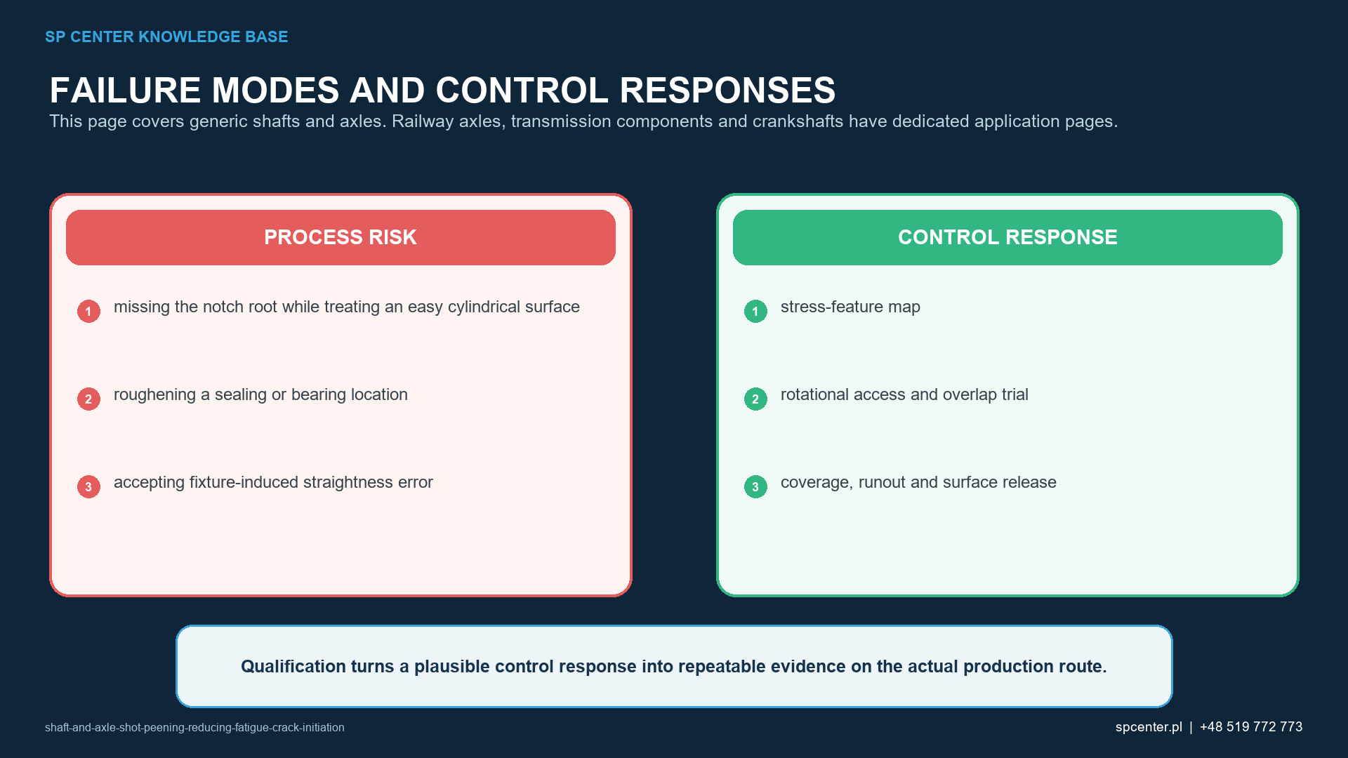
- The outer diameter appears complete, but a fillet, keyway root or spline flank remains shadowed.
- Uncontrolled dwell or overlap roughens an edge, thin feature, journal or seal track.
- Media remains in an oil hole, cross-hole or internal passage.
- The wrong fixture, program, diameter family or part revision is used.
- Runout or clamping changes the stream distance around the circumference.
- A prior crack, grinding burn, decarburized layer or corrosion defect is treated as though peening repaired it.
- Post-peening grinding, straightening or thermal exposure changes the qualified result.
Stop and contain product from the last verified acceptable state. Preserve the machine, media, tooling, program and inspection evidence, determine the affected scope and obtain the required engineering or customer disposition. Repeening is not an automatic correction because cumulative exposure, roughness, dimensions and material response may limit rework.
What should an RFQ or purchase order define?
| RFQ input | Why it matters | Typical ambiguity prevented |
|---|---|---|
| Controlled drawing, part number and revision | Defines identity, treatment zones, exclusions and boundaries | Peening the wrong surface or obsolete configuration |
| Material, heat treatment and incoming condition | Controls damage risk and process response | Using one route across unlike material states |
| Prior and subsequent operations | Grinding, straightening, coating, plating and thermal exposure can change the result | Removing or relaxing the treated layer after peening |
| Intensity, strip type, coverage and media | Defines the required process outputs | Treating machine pressure or cycle time as the requirement |
| Surface, dimensional and cleanliness limits | Protects journals, bores, threads, fits and oil paths | Releasing a part on intensity and coverage alone |
| Quantity, lot logic and records | Supports capacity, traceability and release planning | An incomplete quotation or undocumented batch release |
Table 3. Complete input lets the supplier quote feasibility and qualification without inventing a process requirement.
Also identify the critical load-bearing features, maximum and minimum diameters, length, mass, hole or bore cleanliness, available handling datums, packaging needs and required customer approvals. Where a requirement conflicts or a revision is missing, processing should wait for controlled clarification.
Frequently asked questions
Why are shafts and axles shot peened?
When the controlled design invokes the process, shot peening can introduce compressive residual stress in fatigue-sensitive surface zones and may delay surface crack initiation. The benefit remains specific to material, geometry, loading, surface condition and the qualified route.
Are a shaft and an axle the same component?
Not necessarily. A shaft commonly transmits torque, while an axle commonly supports rotating elements and may itself be stationary or rotating. Terminology varies, so function, drawing and load case must control the review.
Which shaft features are usually most critical?
Fillets, shoulders, diameter transitions, keyway or spline roots, holes, threads, press fits and fretting zones often deserve review. The drawing and stress assessment determine the actual treatment zones.
Can correct Almen intensity prove a fillet is covered?
No. Intensity verifies the stream at defined test locations. Coverage and access at the real fillet, keyway, spline or hole require component-specific evidence.
Should bearing and seal seats always be masked?
No universal rule applies. The controlled drawing, specification, customer requirement or approved technical decision must define whether each precision surface is treated, excluded or protected.
Can shot peening repair a crack, grinding burn or decarburized layer?
No. Existing defects require detection and disposition by the applicable design or repair authority. Peening cannot make an unacceptable incoming condition acceptable by itself.
Can a shaft be ground or straightened after peening?
Only when the approved manufacturing route permits it. Material removal can remove the beneficial layer, straightening can change stress and geometry, and thermal operations can relax residual stress.
Does shot peening always increase shaft fatigue life?
No universal increase can be promised. A fatigue claim requires validation representative of material, heat treatment, geometry, load spectrum, surface condition and process configuration.
Key takeaways
- Use function, drawing and load case rather than the component name alone.
- Qualify the difficult fillet, root, flank or hole, not only the accessible outer diameter.
- Control rotation, traverse, footprint, overlap, runout and fixture location as one system.
- Place peening correctly relative to grinding, straightening, heat and coating operations.
- Keep intensity, coverage, component condition, residual stress and fatigue evidence separate.
- Do not promise crack repair or a universal increase in fatigue life.
Related SP Center guides
- Crankshaft Shot Peening
- Shot Peening Transmission Components
- Designing for Shot Peening
- Surface Defects and Shot Peening
Technical references
1. SAE J2441_202511: Shot Peening, stabilized November 2025
2. SAE AMS2430U: Shot Peening, revised April 2018
3. SAE ARP7488: Peening Design and Process Control Guidelines, issued January 2018
4. SAE J442_202602: Tools for Peening Intensity Determination and Verification, revised February 2026
5. SAE J443_202512: Procedures for Determining and Verifying Peening Intensity, revised December 2025
6. SAE J2277_202301: Shot Peening Coverage Determination, revised January 2023
Standards note: Use the complete revisions invoked by the drawing, contract and customer flow-down. This guide explains engineering relationships and does not replace controlled requirements.
Author: Paweł Kmieć
Discuss shaft or axle shot peening: +48 519 772 773 | [email protected]