


How to develop treatment zones, access, masking and verification around fatigue-critical crankshaft features
Crankshaft shot peening is a feature-specific surface-enhancement process. Fillets, oil-hole exits and section transitions may be fatigue-critical, but their relevance depends on crankshaft design, material, heat treatment, loading and manufacturing sequence. The objective is to reproduce an authorised treatment on the defined areas without damaging journals, edges, holes, dimensions or previously generated surface conditions.
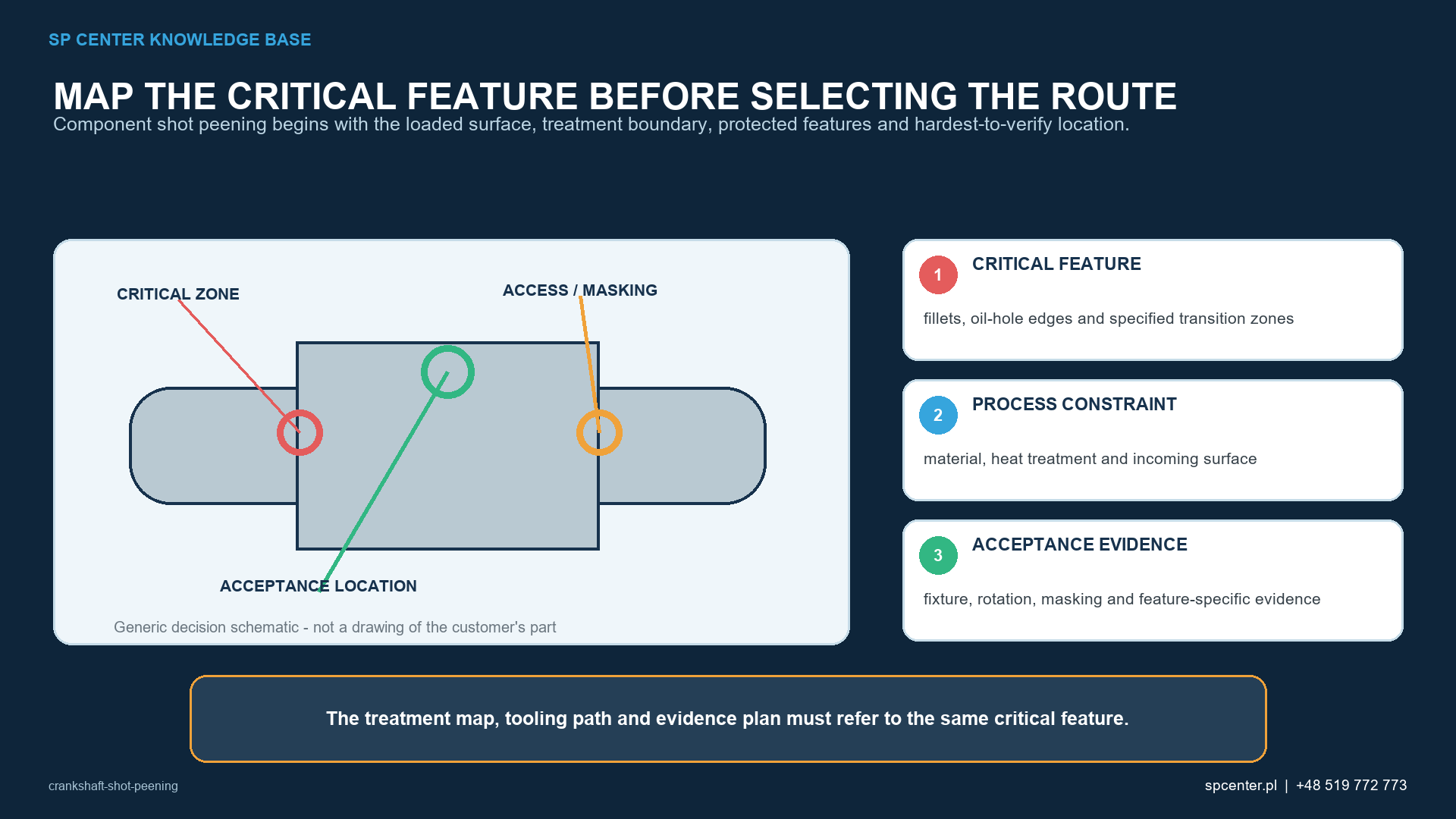
Why should crankshaft shot peening start with the failure mechanism rather than the component name?
Crankshafts experience combined bending and torsional loading, but fatigue initiation location is design- and duty-cycle-specific. Do not assume that every crankshaft fails at the same feature or that the entire component should be peened. Establish treatment areas from authorised engineering evidence and the controlled drawing.
Which crankshaft features require explicit review?
| Feature | Why it may be critical | Process-control question |
|---|---|---|
| Crankpin or main-journal fillet | Geometry can concentrate cyclic stress. | Can the stream reach the full defined radius without damaging the journal? |
| Oil-hole exit | Local geometry and machining condition may raise initiation risk. | Are edge condition, masking and media access explicitly controlled? |
| Section transition | Load path and stiffness change locally. | Where does treatment start/stop, and is the boundary authorised? |
| Journal or sealing surface | May have strict finish and dimensional requirements. | Must it be excluded, protected or inspected after processing? |
Table 1. Potential criticality must be confirmed for the actual crankshaft; this table is not a universal treatment map.
How do material, heat treatment and incoming surface condition affect the process?
Forged steels, micro-alloyed steels, cast irons, induction-hardened and nitrided conditions can respond differently. Hardness, case depth, prior cold work, grinding condition and surface defects influence process development. A qualified process should not be transferred between crankshaft families by nominal similarity alone.
Why is the manufacturing sequence part of the process design?
- Confirm whether peening occurs before or after final grinding, nitriding, induction hardening, fillet rolling, polishing and cleaning.
- Evaluate whether a downstream operation removes or relaxes the intended surface condition.
- Do not assume shot peening and fillet rolling are interchangeable or automatically additive.
- Control the authorised order, intermediate inspection and change-approval route.
ENGINEERING NOTE If fillet rolling and shot peening are both specified, their sequence and interaction require explicit qualification. Each changes the near-surface condition and can affect the response to the next operation.
Why must intensity, coverage and feature access be evaluated separately?
| Control | What it establishes | What it does not prove |
|---|---|---|
| Almen intensity | Standardized response of the peening stream. | Coverage of a crankshaft fillet or acceptable journal condition. |
| Coverage evaluation | Impacted extent of the specified feature under the invoked method. | Correct intensity or qualified cycle duration. |
| Qualified exposure | Production time, passes or cycles for the approved setup. | Coverage acceptance without the prescribed evaluation. |
| Component inspection | Surface, dimensions, boundaries and required feature acceptance. | Unspecified fatigue-life improvement. |
Table 2. A conforming Almen result cannot substitute for evidence from the actual feature.
How should fixturing, motion and masking be controlled?
The process must maintain the required relationship between the stream and each treated feature. Part rotation, indexing, nozzle or wheel position, angle, stand-off distance, media flow and exposure must be controlled. Masking must protect excluded journals, holes or adjacent surfaces without unintentionally shadowing the treatment boundary.
How should surface integrity and dimensional control be addressed?
- Confirm incoming grinding, polishing and edge condition.
- Inspect for excessive indentation, folds, local damage and unintended treatment.
- Verify critical dimensions, runout or distortion where invoked.
- Keep oil holes and passages clean and free from trapped media.
- Apply residual-stress or fatigue validation only when required by the approved qualification plan.
How does shot peening differ from fillet rolling?
Both processes can introduce compressive residual stress, but they use different contact mechanisms, tooling and process controls. Published results for specific materials and specimen geometries cannot be transferred directly to another crankshaft. Selection or combination must follow design authority, manufacturing route and component validation.
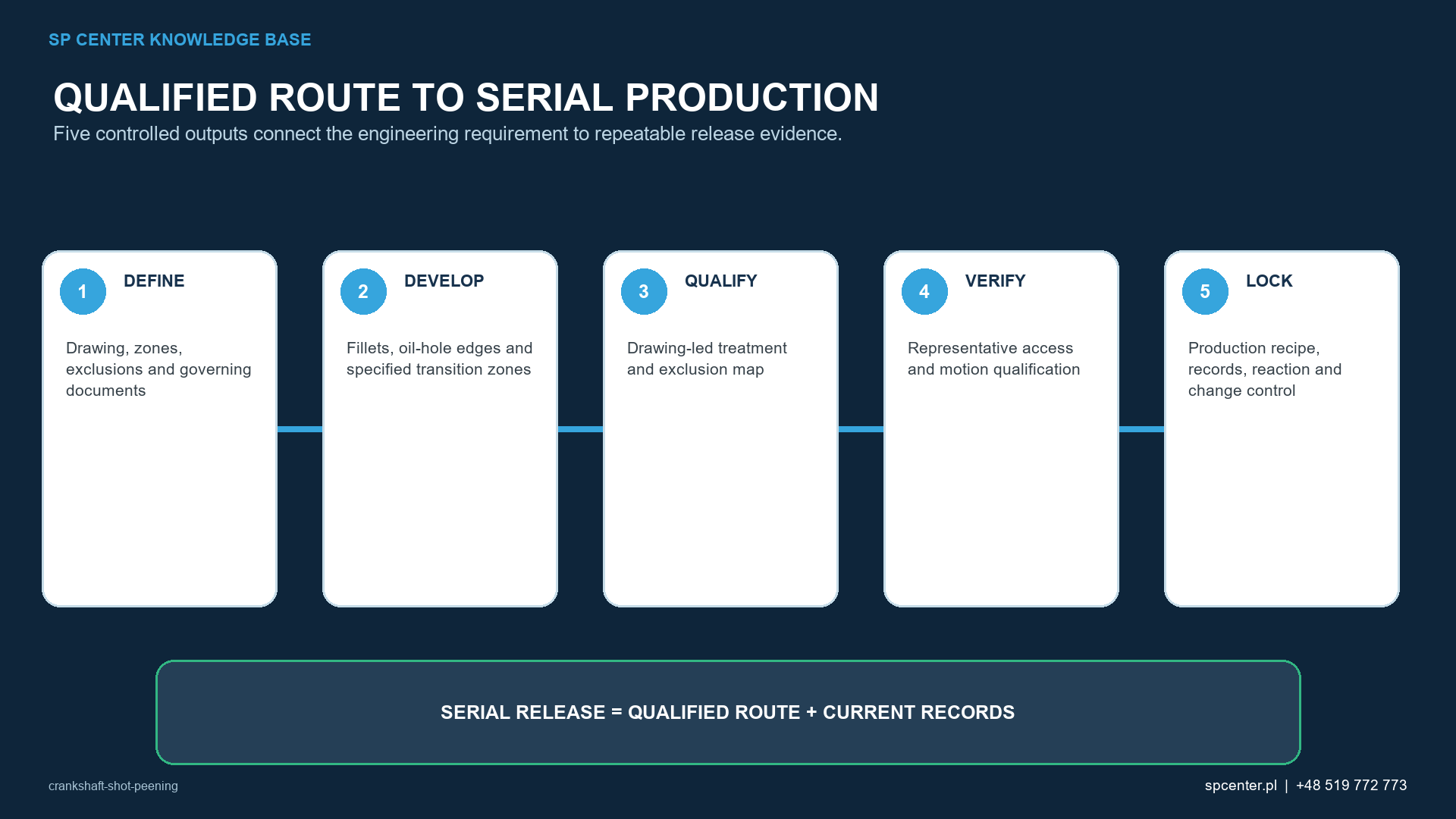
What is a practical qualification sequence?
| Stage | Required output |
|---|---|
| 1. Requirements review | Controlled drawing, material, heat treatment, areas, exclusions and process order. |
| 2. Feature and access review | Critical radii, holes, boundaries, masking and inspection route. |
| 3. Process development | Media, equipment, motion, saturation/intensity and coverage/exposure evidence. |
| 4. Component evaluation | Surface integrity, dimensions, cleanliness and required validation. |
| 5. Serial control | Approved setup, media controls, records, reaction plan and change management. |
Table 3. Each stage closes a different crankshaft-specific risk.
How should crankshaft shot peening be specified and qualified?
Qualification must connect the actual component to a controlled production route. For crankshaft shot peening, the technical review should address fillets, oil-hole edges and specified transition zones, material, heat treatment and incoming surface, fixture, rotation, masking and feature-specific evidence. A successful trial is not transferable when the equipment, media, tooling, geometry, motion, preparation or acceptance method changes without review.
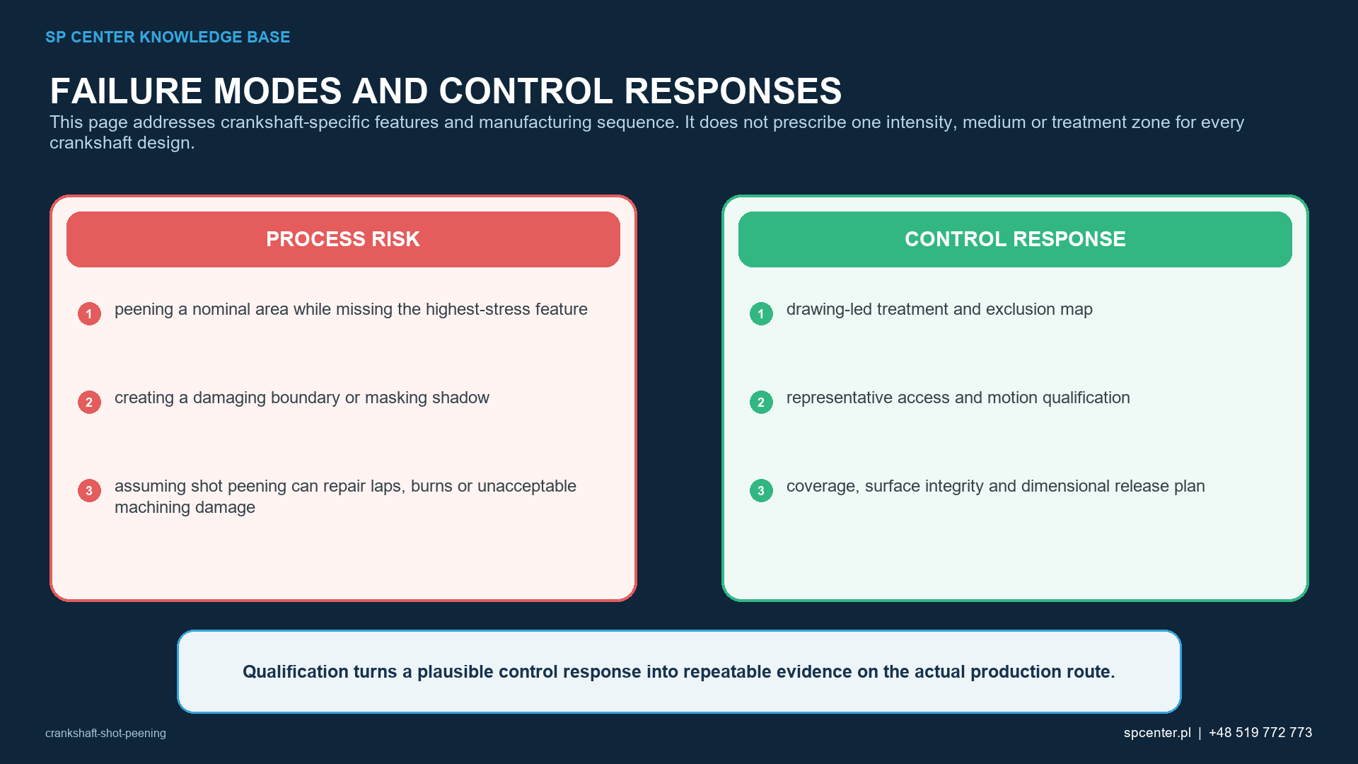
The release plan should address the component-specific risks: peening a nominal area while missing the highest-stress feature, creating a damaging boundary or masking shadow, assuming shot peening can repair laps, burns or unacceptable machining damage. SP Center can propose feasibility work and a process-control route, but the drawing, invoked specifications, approved deviations and customer flow-down remain the contractual authority.
| RFQ input | Why it matters |
|---|---|
| Controlled drawing and revision | Defines the part identity, treatment zones, boundaries and exclusions. |
| Material, heat treatment and incoming surface | Supports media, damage, roughness, contamination and sequence review. |
| Governing specifications and customer flow-down | Identifies the authority for intensity, coverage, media, records and acceptance. |
| Geometry, size, mass and representative features | Supports feasibility for fillets, oil-hole edges and specified transition zones and the worst-access location. |
| Quantities, lot logic and delivery plan | Allows a production route, capacity plan, traceability level and commercial basis to be defined. |
| Surface, dimensional and record requirements | Prevents intensity or coverage from being treated as the only release evidence. |
Table 4. RFQ inputs for a controlled project review.
RFQ SUPPORT Send the controlled drawing, requirements and quantity to [email protected]. For an initial feasibility discussion, call +48 519 772 773.
Which crankshaft shot peening misconceptions should be avoided?
The assumption “The entire crankshaft should be peened.” is not a reliable engineering rule. The drawing defines scope.
The assumption “Higher intensity always increases crankshaft life.” is not a reliable engineering rule. The qualified window and surface condition govern.
The assumption “Shot peening replaces fillet rolling.” is not a reliable engineering rule. They are different processes.
The assumption “A correct Almen result proves the fillet is correct.” is not a reliable engineering rule. Access, coverage and surface acceptance remain separate.
The assumption “The same process fits every crankshaft.” is not a reliable engineering rule. Material, geometry, heat treatment and sequence matter.
Frequently asked questions about crankshaft shot peening
What is Crankshaft Shot Peening?
Crankshaft shot peening is a feature-specific surface-enhancement process. Fillets, oil-hole exits and section transitions may be fatigue-critical, but their relevance depends on crankshaft design, material, heat treatment, loading and manufacturing sequence.
Which crankshaft areas are commonly reviewed for shot peening?
Crankshaft shot peening reviews normally start with fatigue-critical fillets, transitions, oil-hole edges and any drawing-defined zones. The design authority must identify the required surfaces and boundaries for the actual crankshaft.
Is shot peening the same as fillet rolling on a crankshaft?
Shot peening and fillet rolling are different surface-enhancement routes. They impose different deformation fields, geometry constraints, tooling requirements and qualification evidence, so one should not be substituted for the other without design approval.
Which variables control crankshaft shot peening?
Crankshaft shot peening depends on fillets, oil-hole edges and specified transition zones, material, heat treatment and incoming surface, fixture, rotation, masking and feature-specific evidence. The production route must also control drawing-led treatment and exclusion map, representative access and motion qualification, coverage, surface integrity and dimensional release plan.
Does correct Almen intensity prove crankshaft shot peening is acceptable?
Correct Almen intensity proves only the standardized stream response required by the invoked procedure. This page addresses crankshaft-specific features and manufacturing sequence. It does not prescribe one intensity, medium or treatment zone for every crankshaft design.
What should an RFQ for crankshaft shot peening include?
Send the controlled drawing and revision, material and heat treatment, required treatment and exclusion zones, governing specifications, intensity and coverage requirements, quantities, surface and dimensional limits, and required records.
Which standards apply to crankshaft shot peening?
The applicable documents depend on the contract and component. Relevant technical references include AMS2430U, ARP7488, SAE J443_202512 and SAE J2277_202301, but the revisions invoked by the drawing and customer flow-down remain authoritative.
Can SP Center assess a crankshaft shot peening requirement?
Yes. SP Center can review feasibility, process controls, trials, qualification evidence and serial requirements within its confirmed capability and approval scope. Call +48 519 772 773 or send the controlled documentation to [email protected].
What are the key takeaways?
- Treat only authorised fatigue-critical areas.
- Control the full manufacturing sequence, including grinding, heat treatment and fillet rolling.
- Keep Almen intensity, coverage, qualified exposure and component release separate.
- Validate actual fillet and oil-hole access.
- Protect functional surfaces and verify cleanliness and dimensions.
Which related SP Center guides should be read next?
Which technical references support this guide?
1. SAE AMS2430U: Shot Peening, revised April 2018
2. SAE ARP7488: Peening Design and Process Control Guidelines, issued January 2018
3. SAE J443_202512: Procedures for Determining and Verifying Peening Intensity, revised December 2025
4. SAE J2277_202301: Shot Peening Coverage Determination, revised January 2023
6. Burrell, N. K., Controlled Shot Peening of Automotive Components, SAE 850365 (1985).
8. SAE J2441_202511: Shot Peening, stabilized November 2025
REFERENCE CONTROL Use the complete revisions invoked by the drawing, contract and customer flow-down. This article provides engineering context and does not replace controlled requirements.
Author: Paweł Kmieć
Discuss this shot peening requirement: +48 519 772 773 | [email protected] | shot peening service