


How treatment zones, access, masking, material condition and controlled drawing requirements support a feasible production route
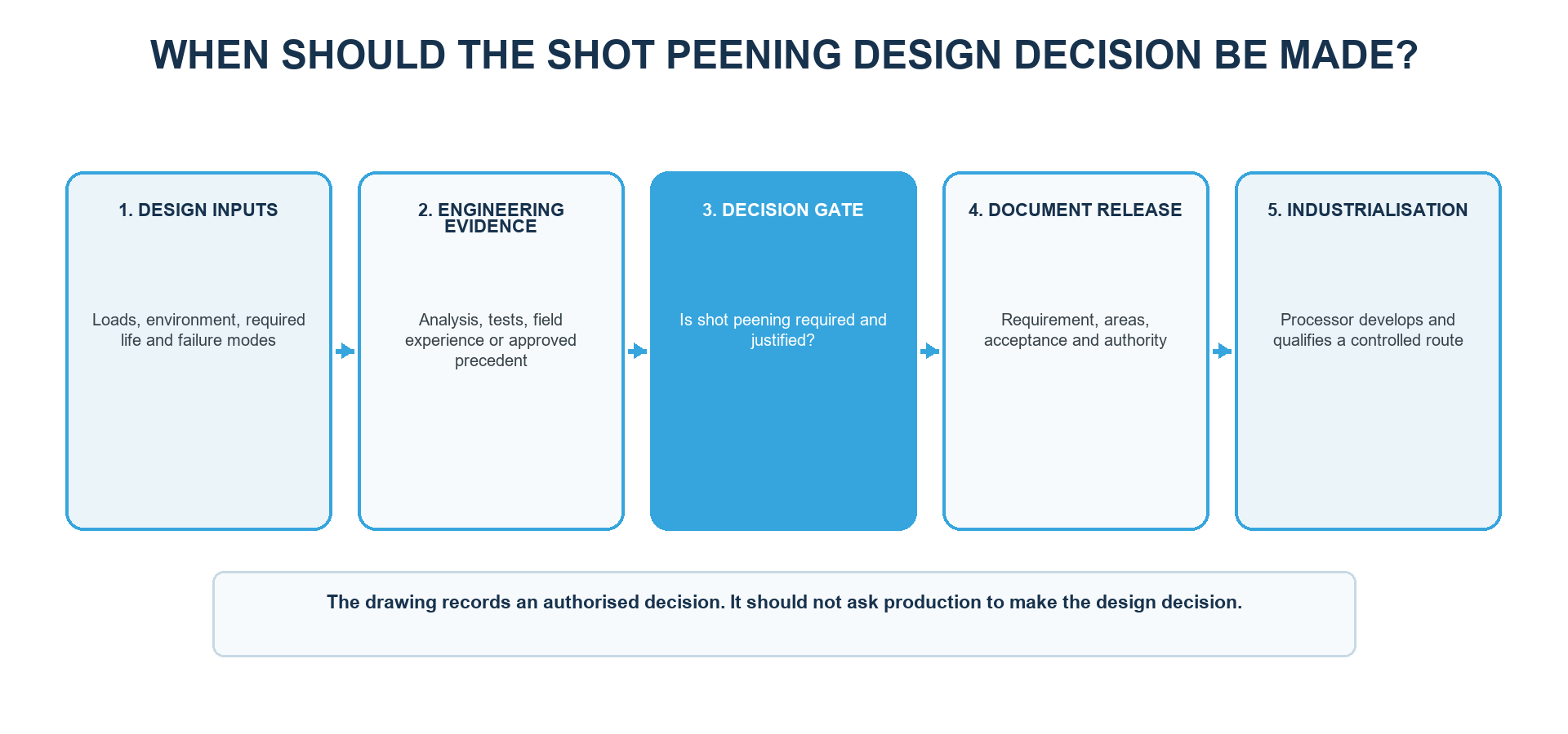
Shot peening should enter a design only after authorized engineering identifies a surface-driven risk or performance objective, reviews suitable evidence and confirms compatibility with material, geometry and manufacturing sequence. The released requirement must define treatment zones, governing documents, complete Almen intensity and coverage requirements, protected features, acceptance evidence, qualification and approval authority. The processor converts those inputs into a controlled production route; the processor must not silently make the design decision.
Why should shot peening be considered before design release?
Shot peening affects treatment boundaries, access, masking, inspection, tooling and manufacturing order. Adding it after drawings and tooling are frozen can expose conflicts such as inaccessible critical features, unprotected functional surfaces or missing qualification evidence. Early review allows design, materials, manufacturing, quality and the processor to resolve these interfaces before production commitments are made.
The decision starts with the component problem, not with process availability. Engineering should identify service loading, environment, required life, stress concentrations, likely crack-initiation sites and relevant failure modes. Shot peening can then be assessed as part of the design solution. It should not hide an incorrect material condition, insufficient section size or unsupported loading assumption.
What evidence can justify the design decision?
| Evidence source | Engineering use | Transfer limit |
|---|---|---|
| Stress and fatigue assessment | Identifies critical locations, load drivers and likely crack-initiation sites | Analysis does not qualify production by itself |
| Component or specimen testing | Compares approved configurations or validates a defined requirement | Geometry, surface, load spectrum and statistical basis control transfer |
| Field or fleet experience | Provides service-relevant behaviour and failure history | Similarity to the new design must be justified |
| Approved design precedent | Supports reuse within defined similarity limits | Material, geometry, loading, sequence and process differences require review |
| Customer or regulatory requirement | Creates contractual or programme flow-down | The exact document, revision and approval route govern |
Table 1. Engineering judgment can combine several evidence sources, but each has defined transfer limits.
Shot peening is most relevant when the risk is linked to a defined surface location and a controlled near-surface compressive residual-stress state addresses the intended mechanism. Fretting, stress-corrosion cracking or contact-related conditions may also be considered where supported, but no blanket benefit should be assumed.
How does geometry affect feasibility?
The peening stream must reach the specified surface with repeatable presentation. Deep recesses, narrow channels, undercuts, adjacent features and abrupt shielding can prevent access or create large changes in impact angle. Thin walls, unsupported edges and asymmetric treatment can also increase distortion risk. A drawing can therefore contain a technically desirable zone that cannot be processed or verified by the proposed equipment.
| Feature | Design question | Potential control |
|---|---|---|
| Fillet or root | Can the critical surface receive repeatable exposure? | Define the zone and access; review fixture and stream presentation |
| Hole or recess | Is direct treatment required, prohibited or impractical? | Define treatment, exclusion, masking and media removal |
| Thread or precision fit | Could impacts affect function or dimensions? | Protect explicitly and define the boundary |
| Sharp edge | Is edge damage or local overworking a risk? | Define edge condition, protection and trial review |
| Thin or flexible section | Can treatment cause distortion? | Support strategy, balanced presentation and dimensional verification |
| Sealing or contact surface | Could topography change affect function? | Masking plus separate roughness and dimensional criteria |
Table 2. Geometry connects the fatigue-critical location to access, protection, tooling and verification.
How should treatment zones be shown?
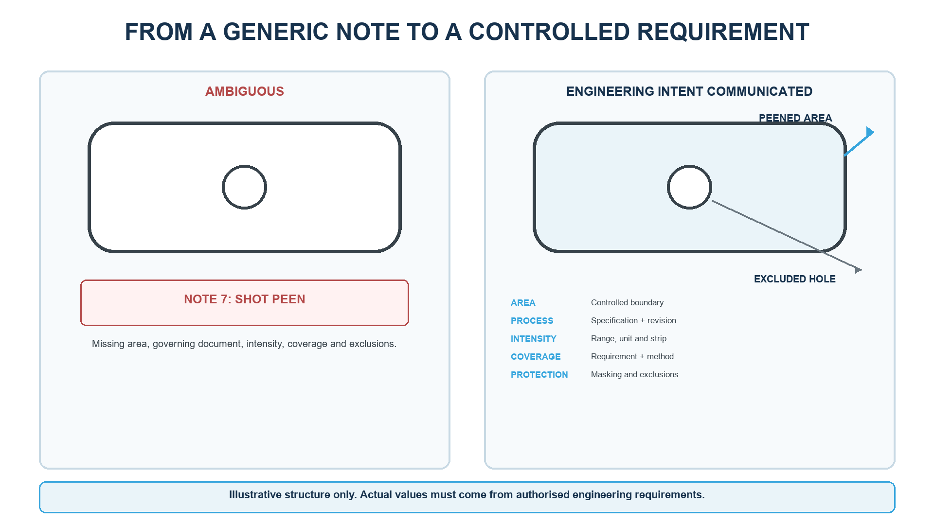
Use controlled drawing views, sections, dimensions, datums, zone identifiers or model-based definitions to show where direct impact is required. Mark excluded surfaces, holes, threads, fits, sealing faces, finished interfaces and protected edges. If the transition between treated and untreated areas affects function, define its location and permitted variation.
A note such as “shot peen part” is incomplete because it does not define boundaries, exclusions, the transition, masking or acceptance. The requirement may be distributed across drawings, process specifications and quality documents, but identifiers, revisions, terminology and precedence must remain consistent.
Which features need protection or special review?
- Threads, bearing seats, precision fits and sealing faces where topography or dimensions affect function.
- Small holes and cavities where access, media entry and removal are difficult.
- Sharp edges and thin sections vulnerable to damage or distortion.
- Finished interfaces with separate roughness or cleanliness limits.
- Closely spaced treated and excluded features that challenge masking and stream presentation.
The processor may develop masks, plugs, fixtures and work instructions within the approved requirement, but the controlled documentation must identify what remains untreated. The supplier should not be expected to infer every protected feature from tolerances alone.
How do material condition and sequence affect the design?
| Operation or condition | Design interface | Review question |
|---|---|---|
| Heat treatment and hardness | Control material response and damage sensitivity | Is the released condition the one presented for peening? |
| Machining or grinding | Can remove the affected layer or change critical geometry | Does material removal occur before or after peening? |
| Thermal exposure | Can relax residual stress | Are temperature and time compatible with the design basis? |
| Coating or plating | Creates sequence, adhesion, masking and compatibility constraints | Which operation occurs first under the governing requirement? |
| Cleaning and media removal | Affect contamination and retained-media risk | Are cavities and material compatibility controlled? |
| Final inspection | Must address the property and evidence actually required | Which results are process controls and which are component acceptance? |
Table 3. Material condition and downstream operations can change or remove the intended treated state.
The design package should identify the material specification, product form, heat treatment and hardness where relevant. It should also position shot peening relative to machining, grinding, thermal processing, coating, plating, cleaning, repair and final inspection. If a downstream operation changes, engineering must review whether the qualification remains applicable.
How should fatigue and residual-stress objectives be documented?
“Improve fatigue life” is useful engineering context but not a complete production requirement. It does not define zone, intensity, coverage, material condition, sequence, evidence or acceptance. Process conformity and component performance remain separate decisions.
Almen intensity and coverage demonstrate selected aspects of a controlled production route. They do not by themselves prove a residual-stress profile or fatigue-life multiplier in the component. If residual stress, roughness, hardness, dimensions or fatigue performance are acceptance characteristics, define the method, location, specimen or component, preparation, limits and approval authority.
What should the drawing state about intensity and coverage?
Specify a complete Almen intensity range with strip designation and units or notation convention, plus a separate coverage requirement for each relevant zone. A bare value such as “0.012” is ambiguous, and machine pressure or wheel speed is not a substitute for Almen intensity. Complete coverage does not prove intensity; a conforming intensity result does not prove every component surface was treated.
What must the controlled requirement set communicate?
| Requirement group | Information to control | Release question |
|---|---|---|
| Engineering objective | Function, critical location and failure mechanism | Why is shot peening required? |
| Scope | Treated surfaces, boundaries, exclusions and transitions | Where does direct impact apply? |
| Governing documents | Specifications, customer clauses, revisions and precedence | Which controlled set governs? |
| Process targets | Complete Almen intensity and separate coverage requirement | What must the process achieve? |
| Component condition | Material, product form, heat treatment, hardness and sequence | What condition is processed? |
| Protection | Masking, holes, threads, fits, edges and retained-media controls | What must remain unaffected? |
| Evidence | Records, traceability, inspection, retention and release | What proves conformity? |
| Qualification and responsibility | Trials, approvals, open-point ownership and change control | Who may decide each item? |
Table 4. The controlled set must answer why, where, what, how conformity is demonstrated and who approves.
Who owns the design decision and who develops the process?
| Authorized engineering or customer | Processor or manufacturing |
|---|---|
| Defines the functional requirement and component design values | Develops a capable process within approved requirements |
| Identifies treatment zones, exclusions and acceptance criteria | Develops tooling, masking, settings and work instructions |
| Approves design values, deviations, changes and supplier proposals | Documents proposals and waits for the required approval |
| Controls material, geometry and sequence interfaces | Maintains equipment, media, verification and traceability |
| Defines component validation and qualification evidence where required | Produces the requested qualification and production records |
Table 5. The exact split is contractual, but design responsibility and process development must remain explicit.
Open items should be documented with the affected document, question, proposed resolution, responsible authority and impact on cost, timing, tooling or qualification. Production must not start while an unresolved item can change treatment or acceptance.
Which changes require technical review?
Changes to geometry, treatment boundaries, material, product form, heat treatment, hardness, sequence, coating, thermal cycle, intensity, coverage, media restrictions, masking, supplier, equipment, tooling, program or evidence can affect the qualified route. The change record should state what changed, why existing evidence remains valid or what new evidence is required, who approved the decision and which controlled documents were revised.
When should shot peening not be added?
- No authorized surface-driven objective or evidence basis exists.
- The critical area cannot be treated, protected or verified.
- Distortion, functional-surface or retained-media risk cannot be controlled.
- The process is being used to conceal another design or manufacturing deficiency.
- A downstream operation removes or materially relaxes the treated state without validation.
- Design change, qualification impact or approval authority remains unresolved.
Frequently asked questions
At what design stage should shot peening be considered?
Consider it before design release, while treatment zones, access, protected features, material condition, sequence, qualification and acceptance evidence can still be coordinated.
What information does a processor need from the designer?
Provide controlled geometry, material and heat-treatment condition, treatment and exclusion zones, governing documents, complete intensity and coverage requirements, sequence, quantities, evidence and approval route.
Can a supplier choose the Almen intensity for a new part?
Only when the contract explicitly authorizes the supplier to propose it. The design or specification authority must approve any design-controlled value before production release.
How should a shot peening area be marked on a drawing?
Use controlled views, zones, dimensions, datums or model-based definitions. Show boundaries, exclusions, masking and transition requirements where they affect function or inspection.
Does shot peening require a universal dimensional allowance?
No. The need depends on geometry, stiffness, surface function, material and qualified process. Sensitive dimensions require engineering review and appropriate verification.
Should holes and threads be shot peened?
Only when the approved design requires treatment and the feature can be processed and inspected. Otherwise mark the feature as excluded and define the masking and boundary controls.
Can shot peening be added after machining is complete?
It can be added only through controlled design and process change. Later grinding, machining, finishing or thermal operations must be reviewed because they can alter the treated layer.
Does a shot peening specification prove improved fatigue life?
No. It controls the production process. A fatigue-life claim requires an authorized design basis, representative testing or another approved component-validation route.
Which design changes can trigger requalification?
Changes to geometry, material, heat treatment, hardness, sequence, treatment zones, intensity, coverage, media, masking, supplier, equipment or acceptance evidence can require review under the governing change-control plan.
Key takeaways
- Start with the surface-driven engineering problem and critical location.
- Make the decision before document release and define the supporting evidence.
- Treat zones, exclusions, access, masking and sequence as one controlled requirement set.
- Specify complete Almen intensity and separate coverage requirements.
- Keep process conformity separate from residual-stress or fatigue validation.
- Maintain clear design authority while allowing the processor to develop a controlled production route from approved inputs.
Related SP Center guides
Technical references
1. SAE ARP7488: Peening Design and Process Control Guidelines, issued January 2018
2. SAE AMS2430U: Shot Peening, revised April 2018
3. SAE AMS2432E: Shot Peening, Computer Monitored, revised October 2022
4. SAE J2441_202511: Shot Peening, stabilized November 2025
5. SAE J442_202602: Tools for Peening Intensity Determination and Verification, revised February 2026
6. SAE J443_202512: Procedures for Determining and Verifying Peening Intensity, revised December 2025
7. SAE J2277_202301: Shot Peening Coverage Determination, revised January 2023
Standards note: Use the complete revision invoked by the drawing, contract and customer requirements.
Author: Paweł Kmieć
Discuss your design-for-shot-peening requirement: +48 519 772 773 | [email protected]