


Define the angle convention, model the local trajectory and qualify access at the least accessible specified surface
Impact angle in shot peening is a local geometric condition, not simply the angle shown on a nozzle setting. Particle trajectory, surface normal, component curvature, stand-off, fixtures, masks and motion determine how the stream reaches each point. The selected configuration must achieve the invoked Almen intensity and component coverage while protecting surface integrity and dimensions. No single angle is universally correct.
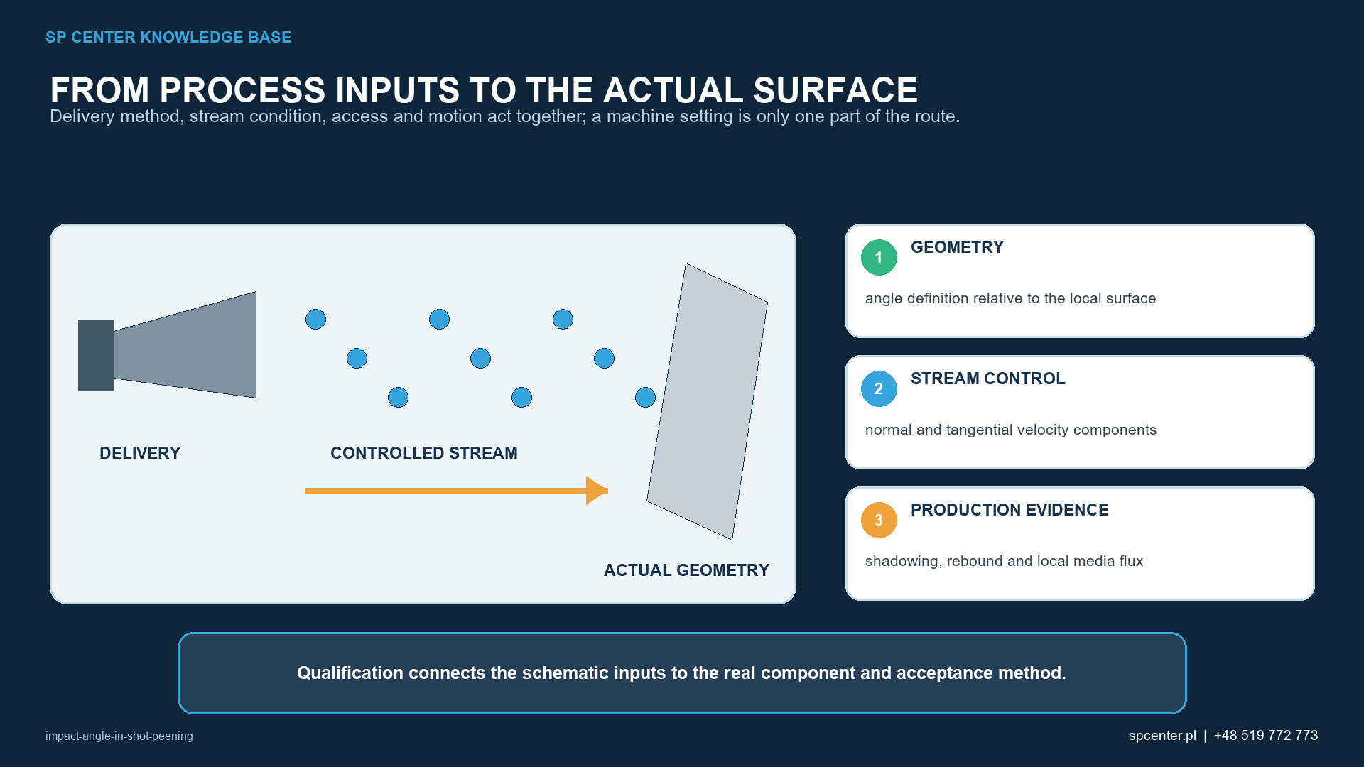
How should impact angle be defined?
| Term | Controlled meaning | Typical ambiguity |
|---|---|---|
| Nozzle or tool orientation | Direction of the nozzle, lance, deflector or wheel coordinate system relative to a component datum | It is not necessarily the mean particle trajectory at the surface |
| Local surface normal | Perpendicular direction at the evaluated point | It changes continuously on curved or radiused surfaces |
| Local impact angle | Angle between incoming particle trajectory and a stated local surface reference | An angle to the plane and an angle to the normal add to 90 degrees |
| Angular distribution | Range of particle trajectories within the usable stream | A real stream is not one ideal ray |
| Stand-off | Distance measured between defined equipment and component references | A nominal value can vary across a curved feature |
| Particle flux | Particles or media mass reaching a local area over time | Machine media flow does not prove local delivery to a shadowed surface |
Table 1. Geometry must be defined before an angle can be specified, measured or compared.
Some documents express angle from the surface plane; others use the surface normal. A reported value is therefore incomplete without its reference. On a radius, tooth root, bore or blade, the local normal changes from point to point. A fixed nozzle orientation can consequently generate a range of local impact angles.
Why do normal and oblique impacts differ?
For an idealised trajectory, particle velocity can be resolved into components normal and tangential to the local surface. A more oblique trajectory generally reduces the normal component and raises the relative tangential component. Real deformation also depends on particle size, shape, hardness and velocity; material and heat treatment; restitution and friction; surface condition; angular spread; local flux; and repeated impacts.
This decomposition explains why indentation shape, directional marking, roughness and coverage rate can change. It does not by itself predict Almen intensity, residual-stress depth, surface damage or fatigue performance. Those outputs require the methods and evidence invoked for the actual process and component.
How does impact angle relate to Almen intensity?
The Almen system characterises peening intensity through the response of the specified strip in its defined holder and stream configuration. SAE J442 defines tools for intensity determination and SAE J443 defines the current method for deriving and verifying intensity. Changing stream orientation relative to the strip can change its response.
A conforming Almen result at one verification location does not prove that every curved, recessed or masked component surface receives the same trajectory or local particle flux. Keep intensity verification, component access, coverage and residual-stress evidence as separate control layers.
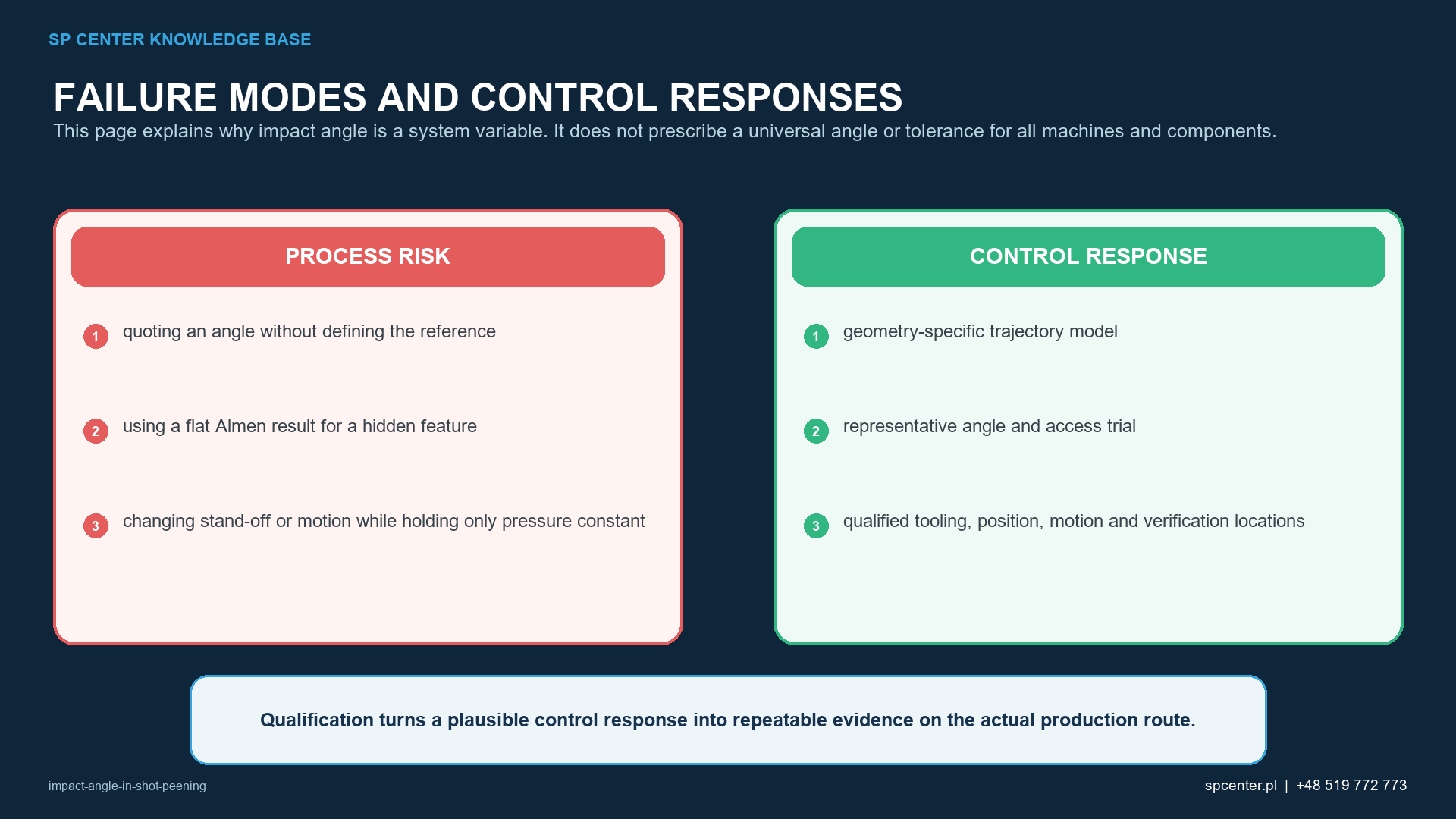
Why are shadowing and coverage not just exposure-time problems?
A surface can remain incompletely covered because the stream is blocked, arrives with unsuitable geometry or provides insufficient local flux. Extra time may add impacts to accessible areas without reaching the hidden feature. The reaction must address the actual geometry rather than automatically increasing exposure.
| Observed result | Geometry question | Controlled response |
|---|---|---|
| Open face covered; recessed fillet incomplete | Can useful trajectories reach the complete specified fillet? | Revise direction, tooling, part motion or media within an authorised development route |
| Coverage changes around a cylinder | Do local angle, stand-off and footprint change during rotation? | Coordinate orientation, rotation, traverse, overlap and exposure |
| Incomplete band next to a mask | Does the mask edge create an unintended shadow or rebound zone? | Redesign the boundary and requalify the applicable configuration |
| Directional marking or roughness shift | Has tangential interaction or angular spread changed? | Contain affected product and assess equipment, path, media and surface acceptance |
| Repeatable pattern displacement | Did datum, fixture, nozzle, deflector or program position move? | Apply the reaction plan; do not compensate by exposure time alone |
Table 2. Coverage patterns can reveal geometry or equipment changes, but disposition follows the approved reaction plan.
Which geometry variables must be controlled together?
Nozzle position can change angle, stand-off, footprint and local flux at the same time. On curved parts, maintaining one machine distance may still change the local geometric relationship. The qualified route therefore connects component datum, fixture, tool coordinates, usable stream, path, rotation, traverse, overlap and exposure.
For air-blast equipment, nozzle or lance condition and alignment are relevant. For wheel equipment, the qualified throwing pattern, wheel condition and component presentation govern a different delivery system. Their settings are not directly interchangeable.
| Feature | Access challenge | Development focus |
|---|---|---|
| Gear-tooth root | Adjacent teeth restrict line of sight to both sides of the fillet | Media size, delivery directions, indexing and root-specific coverage |
| Narrow fillet or shoulder | The adjoining face changes the local normal and can block the stream | Multiple orientations, path following and boundary control |
| Internal diameter | External delivery may not generate suitable internal trajectories | Qualified lance, deflector or internal rotating tool |
| Cross-hole, groove or pocket | Rebound, retention and shadowing can coexist | Dedicated tooling, sequence, cleaning and feature-level evidence |
| Curved shaft or blade surface | Angle, stand-off and footprint vary along a fixed path | Coordinated tool orientation, traverse and component motion |
Table 3. The least accessible specified feature, not the easiest visible face, drives access development.
What surface risks can an unsuitable angle create?
Oblique interaction can alter indentation shape, directional texture and roughness. Rebound can concentrate impacts elsewhere or carry media into a protected region. Edges, thin walls, coatings, machined fits and highly finished surfaces may require feature-specific limits, masking and inspection.
Do not infer an equivalent residual-stress profile from similar nominal machine settings or from coverage alone. When the design invokes a residual-stress, roughness, dimensional or fatigue result, use the authorised component-specific validation and acceptance method.
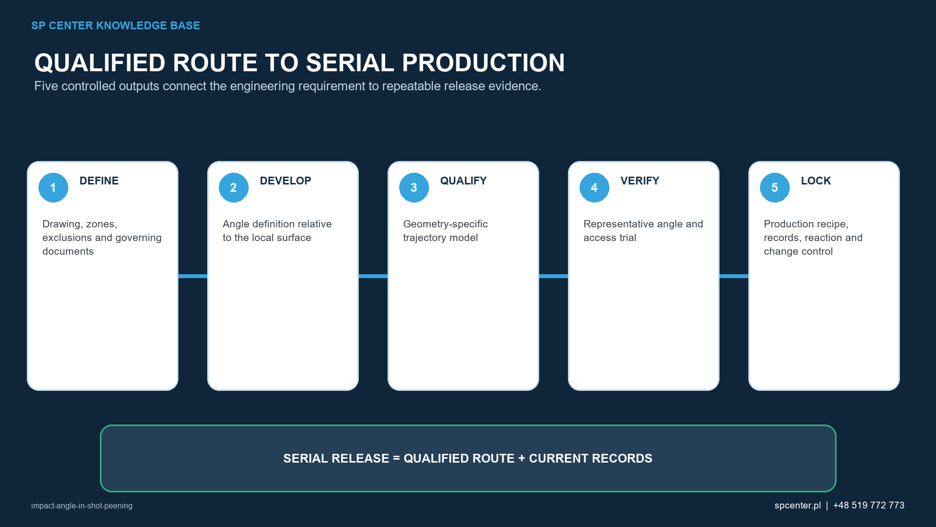
How should impact-angle geometry be qualified?
| Qualification stage | Required output | Evidence boundary |
|---|---|---|
| Requirements definition | Treatment/exclusion map, critical features, angle convention, datum and invoked limits | A standalone angle value is not a complete requirement |
| Representative access trial | Actual or authorised representative geometry, tooling, media and worst-access locations | An open coupon cannot demonstrate a hidden feature |
| Stream qualification | Valid saturation curve and intensity verification for the applicable setup | Almen response is not a component coverage or residual-stress map |
| Component acceptance | Approved coverage method plus surface, damage, cleanliness and dimensional checks as invoked | Complete coverage does not prove an identical subsurface stress profile |
| Production control | Locked program, coordinates, fixture, stand-off, maintenance, monitored variables and reaction plan | Automation repeats the programmed path, whether correct or incorrect |
| Change review | Assessment and requalification trigger for geometry, equipment, program, tooling, media or acceptance changes | Previous evidence is not automatically transferable |
Table 4. Qualification connects machine geometry to component-level evidence and controlled serial production.
What belongs in the controlled process record?
- Part and drawing revision, material, heat treatment and incoming surface condition.
- Treatment, transition, exclusion and mask zones plus critical and least-accessible verification locations.
- Angle convention, component datum, fixture, tool position, stand-off, path, rotation/traverse, overlap and program revision.
- Equipment, nozzle/deflector or wheel configuration, media identity and condition, mass flow and monitored variables.
- Valid saturation/intensity records and approved component coverage, surface, cleanliness and dimensional results.
- Maintenance, alarms, nonconformances, authorised adjustments, change reviews and final release traceability.
What is impact angle in shot peening?
It is the direction of an incoming particle relative to a clearly stated local surface reference at the impact point. The requirement must say whether the angle is measured from the surface plane or the surface normal.
Is 90 degrees always the best shot peening angle?
No. The convention may be ambiguous, and real parts require qualified access, coverage and surface condition. There is no universal optimum angle for every material, feature, medium and machine.
Does an oblique impact reduce intensity?
Changing stream orientation relative to an Almen strip can change the measured response, but angle alone is not a complete process model. Verify intensity by the invoked Almen procedure in the applicable configuration.
Does correct Almen intensity prove component impact angle is acceptable?
No. It verifies standardized strip response for the defined setup. Local trajectory, flux, coverage and surface acceptance at curved or recessed component features require separate evidence.
Can longer exposure correct a poor impact angle?
Not when the critical surface is geometrically blocked or receives unsuitable trajectories. Longer exposure can over-treat open areas while the shadowed feature remains incomplete.
Which variables must be controlled with impact angle?
At minimum review datum and fixture, tool orientation, stand-off, stream footprint, media and mass flow, component motion, path, overlap, masking, exposure and verification locations.
Can a robot guarantee uniform shot peening?
No. A robot can repeat a controlled path, but uniformity still depends on calibrated coordinates, fixture repeatability, tool condition, stream behaviour, component geometry and validated inspection.
What should an RFQ include?
Provide the controlled drawing and revision, material and heat treatment, treatment and exclusion zones, governing specifications, intensity and coverage requirements, geometry, quantities, surface and dimensional limits, and required records.
Key takeaways
- State whether impact angle is referenced to the surface plane or normal.
- Distinguish nominal nozzle orientation from local particle trajectory.
- Control orientation, stand-off, footprint, fixture, media flow and motion as one system.
- Verify coverage at critical and least-accessible specified surfaces.
- Do not treat Almen intensity as proof of component access or residual stress.
- Review geometry, program, tooling and equipment changes through the approved change-control route.
Related SP Center guides
- Shot Peening Coverage
- Shot Peening Saturation Curve
- Exposure Time in Shot Peening
- Masking for Shot Peening
Technical sources
1. SAE J2441_202511: Shot Peening, stabilized November 2025
2. SAE AMS2430U: Shot Peening, revised April 2018
3. SAE ARP7488: Peening Design and Process Control Guidelines, issued January 2018
4. SAE J442_202602: Tools for Peening Intensity Determination and Verification, revised February 2026
5. SAE J443_202512: Procedures for Determining and Verifying Peening Intensity, revised December 2025
6. SAE J2277_202301: Shot Peening Coverage Determination, revised January 2023
Standards note: The editions listed above correspond to the cited publisher catalogue records. The complete revisions invoked by the drawing, contract and customer flow-down remain authoritative; this guide does not assign requirements beyond the accessible publisher scope.
Author: Paweł Kmieć
Discuss impact-angle and access requirements: +48 519 772 773 | [email protected]