


Treat tooth roots, flanks, splines, shaft fillets and notch areas as different engineering features with different fatigue modes, access and acceptance criteria
Shot peening transmission components is not one recipe for an entire gear, shaft or assembly. Tooth roots primarily face bending fatigue; tooth flanks face rolling-sliding contact; splines combine notch stress and fretting; shaft shoulders, keyways and cross holes concentrate bending or torsion. A defensible process maps each required surface to its material state, failure mode, access, surface-function limits and evidence.
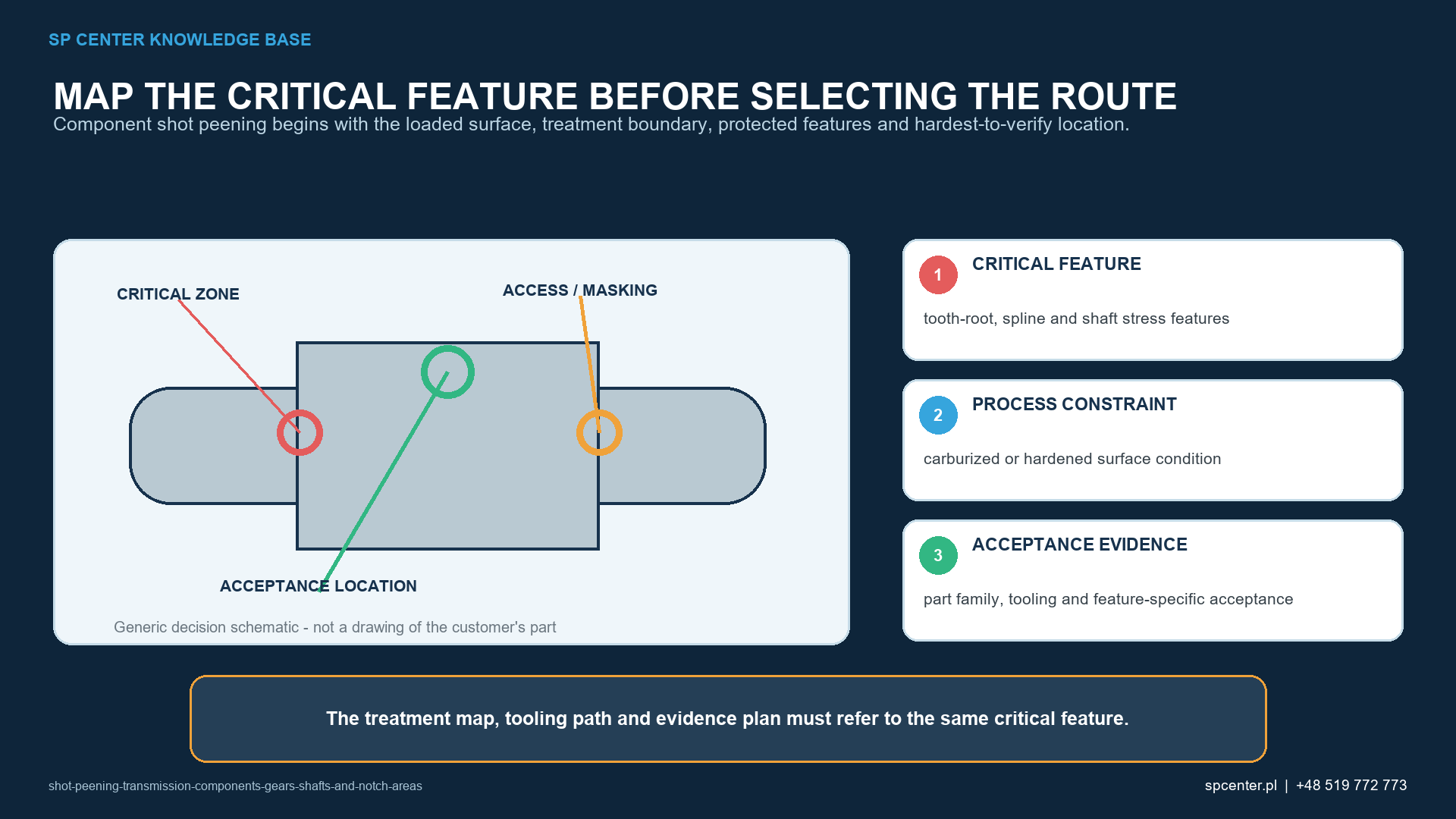
Why is a feature map required?
A drawing callout such as “shot peen all over” can hide conflicting functions. Roughness acceptable in a root may be unacceptable on a seal journal. A nozzle angle that reaches a shaft surface may leave an untreated band in a spline root. The first engineering output is therefore a controlled treatment map with required, protected and transition zones.
The map identifies critical stress directions, local thickness and curvature, heat-treated case, finishing state, masking boundaries, fixture contacts and inspection access. Ambiguous zones require controlled clarification before production.
| Feature | Primary concern | Treatment decision |
|---|---|---|
| Gear tooth root and fillet | Bending-fatigue crack initiation, grinding or heat-treatment damage and restricted line of sight | Map the complete root, select media and angle for access, and verify transition coverage without flank assumptions |
| Gear flank | Contact fatigue, micropitting, lubrication film, topography and retained finishing quality | Peen only when drawing and qualification include the flank; roughness and contact performance require separate evidence |
| Spline root | Torsional or bending concentration, fretting and narrow spacing | Verify circumferential access, tooth-to-tooth repeatability and protection of functional flanks if required |
| Shaft shoulder and fillet | Combined bending and torsion at the radius and transition | Control incidence around the circumference, fixture contact and transition to protected journals |
| Keyway, groove or cross-hole edge | Local notch stress and edge sensitivity | Define edge condition, nozzle access, masking boundary and damage acceptance before peening |
| Bearing, seal or fitted journal | Dimensional, roughness and cleanliness function | Treat or protect only as explicitly required; do not assume every adjacent surface should be peened |
Table 1. Transmission features require different treatment and qualification decisions.
How does the incoming metallurgical condition affect peening?
Carburized, nitrided, induction-hardened and through-hardened components respond differently. Case depth, hardness gradient, retained austenite, intergranular oxidation, decarburization and prior residual stress influence the plastic zone and damage risk.
Shot peening must not be used as a presumed repair for grinding burn, heat-treatment cracks, folds or unacceptable edges. Establish the accepted incoming condition and inspection before the surface appearance is altered by impacts.
How are tooth roots and flanks separated?
The tooth root is a geometric notch subjected mainly to bending. Directed access, small enough media and controlled indexing may be needed to treat the full fillet. Coverage evidence must resolve both sides of every tooth and the transition to any protected zone.
The flank carries contact pressure and sliding. Peening can alter compressive stress, roughness, bearing area and lubrication behaviour. Research results from a particular material, finish and test do not justify universal flank treatment; qualify contact fatigue and topography when the flank is included.
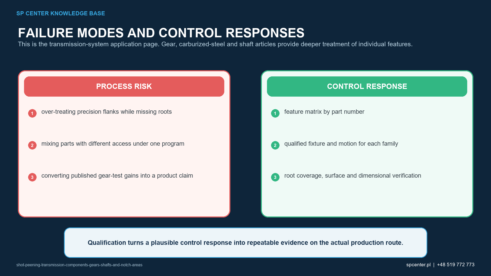
Which process inputs require feature-specific control?
| Input | Why it changes the result | Evidence to control |
|---|---|---|
| Heat treatment and case | Case depth, hardness, retained austenite, decarburization and intergranular oxidation affect plastic response and fatigue | Material and heat-treatment records, hardness and surface-condition acceptance |
| Grinding or machining state | Grinding burn, tensile residual stress, folds and sharp edges can dominate crack initiation | Approved sequence, damage inspection and incoming topography |
| Media size, hardness and shape | Determine access, energy transfer, indentation and stability on hard cases | Specification, operating-mix size and shape, hardness and contamination checks |
| Angle, velocity and flow | Vary locally across roots, splines and shoulders even at one machine setting | Qualified nozzle or wheel geometry, flow and process-response verification |
| Exposure and coverage | Missed bands or double exposure can occur at index and transition zones | Approved coverage method, path overlap and feature-specific inspection |
| Mask and fixture | Can protect functional surfaces but also cause shadowing, rebound and contact marks | Controlled drawing, position, wear limit and boundary verification |
Table 2. Machine setpoints are upstream controls; local impact conditions vary with geometry and access.
Intensity is determined using the specified Almen system and valid saturation curve. It is not identical to pressure, wheel speed or particle velocity. A valid result at the reference location does not prove equal energy in the bottom of a narrow spline or behind a shoulder.
How are shafts, splines and notch areas processed?
Rotate or index shafts so every circumference segment receives the qualified exposure. Control axial transitions, nozzle incidence and fixture contact. For splines, verify tooth-to-tooth access and the root-to-flank boundary. For keyways, grooves and holes, define edge condition and prevent unintended concentration at sharp mask boundaries.
Protect finished journals only according to the approved requirement. Masking can introduce rebound and shadowing; its position and wear are process characteristics, not merely workshop aids.
How are coverage and surface integrity verified?
Coverage is the proportion of the required surface showing impact impressions under the approved method. Use lighting, magnification, replicas, qualified tracer or other authorized technique appropriate to access. Do not infer it from robot path or treatment time alone.
Inspect roots, edges and transitions for folds, sharp indentations, cracks, fretting or mask contact. Roughness and dimensions remain applicable where required. A conforming coverage result does not override surface damage.
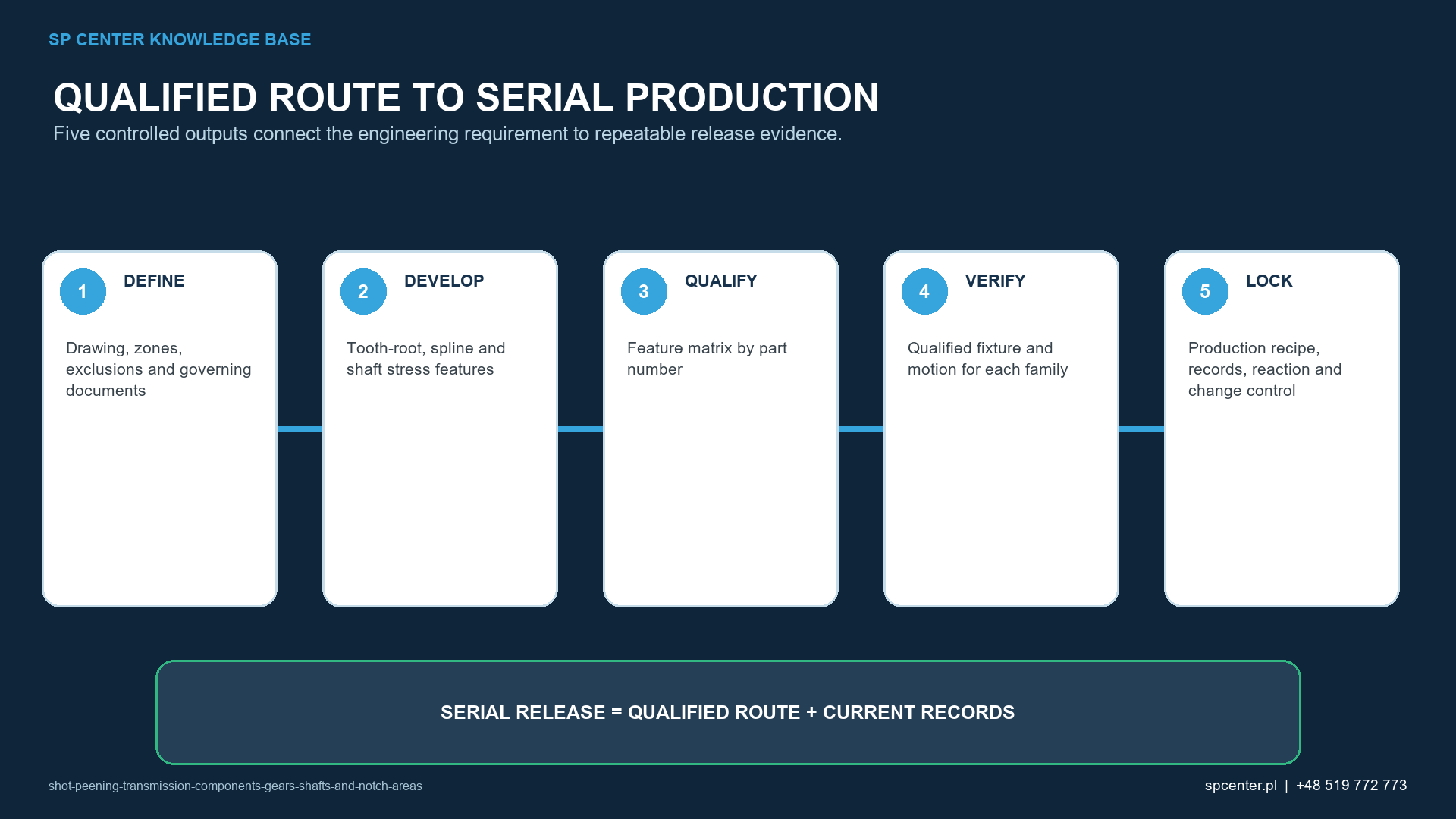
What evidence supports performance claims?
| Performance claim | Relevant evidence | Insufficient evidence alone |
|---|---|---|
| Improved tooth-root bending fatigue | Root residual-stress or cold-work evidence and representative bending-fatigue tests with fracture-origin analysis | Surface stress measured on an accessible flank |
| Improved flank contact fatigue | Topography, residual stress, lubrication-relevant contact testing and micropitting or pitting evaluation | Root-bending coupon results |
| Improved shaft torsional fatigue | Circumferential treatment evidence and representative torsion or combined-load tests | Almen intensity measured away from the feature |
| Reduced fretting at splines | Contact-surface condition, fit, lubrication and representative fretting evidence | Compressive residual stress without contact evaluation |
| Production conformity | Valid intensity, media, coverage, equipment, program, inspection and release records | A prior fatigue study without current process control |
Table 3. Match every durability claim to its actual failure mode and feature.
Residual-stress measurements must identify location, direction, surface preparation and depth method. Fatigue tests should use representative geometry, heat treatment, finish, loading and environment, with fracture-origin analysis. Do not convert a published percentage improvement into a universal design factor.
How does manufacturing sequence affect the result?
Grinding or material removal after peening can remove part of the affected layer. Plating, coating, cleaning and baking after peening can introduce masking, contamination or thermal-stability requirements. Sequence the operations according to the complete drawing and specification.
If a change affects heat treatment, grinding, media, machine, fixture, program, coating cure or part family, review the qualification basis before use. A successful machine trial does not itself grant customer approval.
What belongs in the production control plan?
- Part, material, heat treatment, hardness and finishing traceability.
- Feature-level treatment, protection and transition map.
- Qualified equipment, program, fixture, mask and nozzle or wheel configuration.
- Media specification and operating-mix size, shape, hardness and contamination checks.
- Current saturation curve and production intensity verification.
- Feature-specific coverage, surface and dimensional inspection.
- Alarms, interruptions, rework, deviations and authorized release.
- Records linking every processed lot to the applicable configuration.
Frequently asked questions
Should gear flanks and tooth roots use the same shot peening process?
Not automatically. Roots are often bending-critical, while flanks carry rolling-sliding contact and lubrication requirements. The drawing and qualified process must define each surface.
Can shot peening repair grinding burn or a crack at a notch?
No. Defects require detection and authorized disposition. Peening can change residual stress and appearance but does not erase metallurgical damage or a crack.
Is a conforming Almen intensity enough for a spline root?
No. It verifies a standardized process response at the defined setup. Spline access, coverage, surface condition and any performance claim need feature-specific evidence.
Should bearing and seal journals always be masked?
Only as required by the drawing, specification, approved process or technical disposition. Their dimensional and roughness functions make unintended exposure a risk, but masking is not a universal rule.
Does larger shot always improve gear-root fatigue?
No. Larger media may increase affected depth but can lose access or increase indentation. Media, intensity, angle, case condition and geometry must be qualified together.
Can dual peening be added to a production gear process?
Only as an approved and qualified process change. A second stage changes media, exposure, roughness and residual-stress distribution and is not equivalent to extra coverage.
When should gears be peened relative to grinding and coating?
Follow the controlled drawing and specification route. Material removal after peening can remove the treated layer, while plating, coating or baking can add cleanliness, masking or stress-stability constraints.
How is a complex transmission part qualified?
Use a feature map, safe parameter boundaries, representative parts, feature-specific coverage and surface inspection, dimensions and performance evidence matched to the claimed failure mode.
Key takeaways
- Map each feature to its failure mode and surface function.
- Separate tooth-root bending from flank contact-fatigue requirements.
- Control incoming case, grinding state and defects before peening.
- Verify local access and coverage instead of relying on one Almen value.
- Protect journals and flanks only according to controlled requirements.
- Use feature-representative fatigue evidence for performance claims.
Related SP Center guides
Technical references
1. SAE J2441_202511: Shot Peening, stabilized November 2025
2. SAE AMS2431E: Peening Media, General Requirements, revised April 2023
3. SAE J2277_202301: Shot Peening Coverage Determination, revised January 2023
4. Townsend and Zaretsky, shot peening and surface-fatigue life of carburized AISI 9310 gears, 1988
5. Coryell and Garibay, precision shot peening of hypoid gears, 1996
6. Influence of shot peening on tooth-root bending-fatigue limit of case-hardened gears, 2002
7. Contact-fatigue failure analysis of shot-peened gears, 2002
Standards note: Feature limits, protected areas, sequence, parameters and acceptance follow the complete controlled drawing, specification and customer requirements.
Author: Paweł Kmieć
Discuss shot peening of gears, shafts, splines or notch areas: +48 519 772 773 | [email protected]