


Choose the manufacturing order from the final surface function, grinding integrity, permitted material removal and the evidence required at release
There is no universal rule that shot peening must always come before or after grinding. Peening after final grinding often preserves the treated near-surface layer, but it can also change roughness and precision geometry. Grinding after peening can remove or alter that layer. The defensible sequence is therefore the one authorized by controlled design data and qualified on the actual material, geometry, finishing route and acceptance methods.
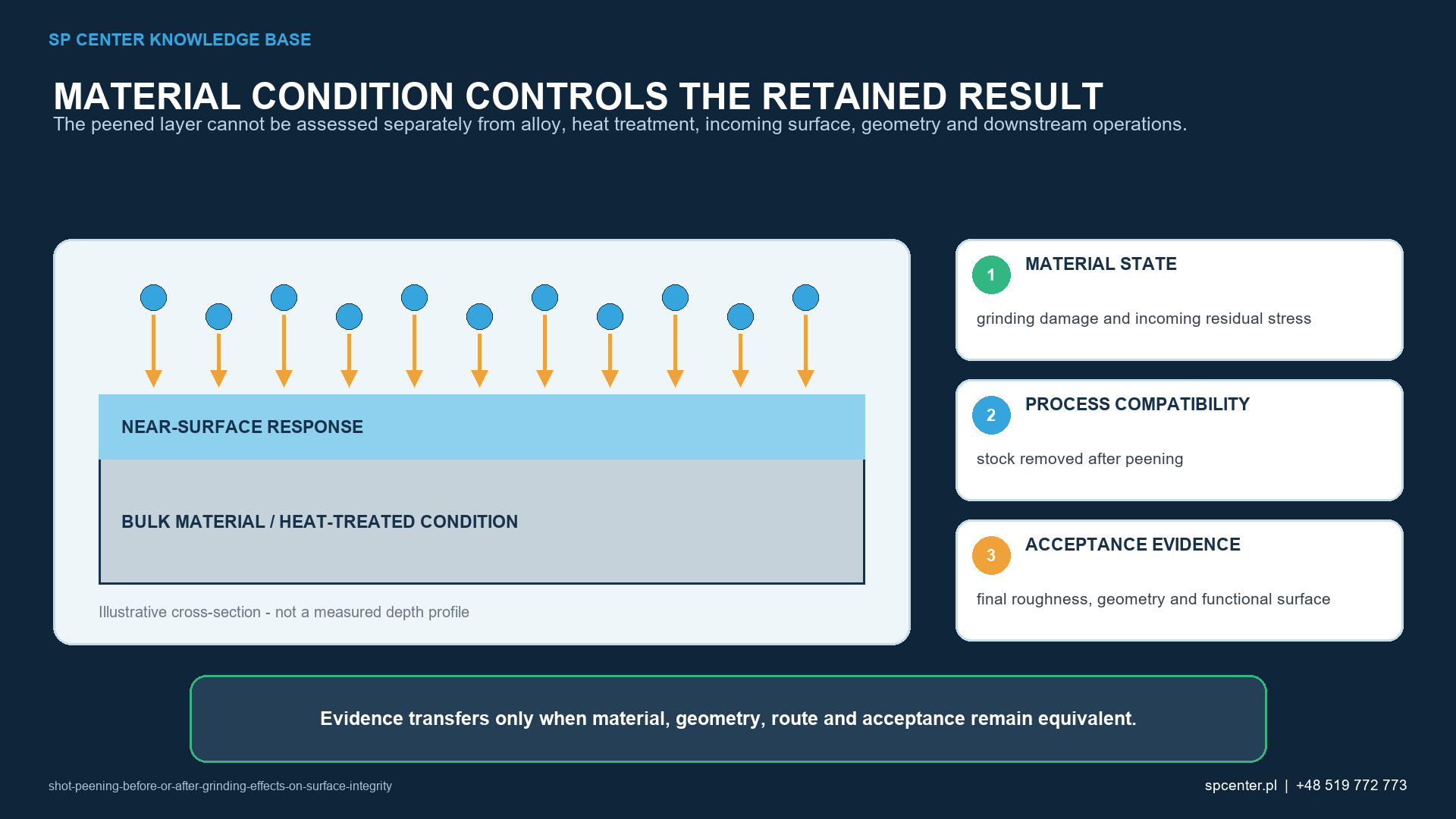
What decision does the grinding-peening sequence control?
Grinding establishes dimensions, form and surface texture, but an unsuitable operation can also produce thermal damage, cracks, smeared material or an unfavorable residual-stress condition. Shot peening plastically affects the near-surface region and is normally specified to introduce compressive residual stress. The two processes interact through the condition that each receives from the previous step.
The sequence review must identify the final fatigue-critical surface, the amount of material removed at every later operation and the inspection state at which each requirement applies. “Peen after machining” is incomplete when the route also contains honing, lapping, polishing, superfinishing or blend repair.
| Candidate route | Potential reason | Required controls and limits |
|---|---|---|
| Final grind, inspect, then peen | Preserves the peened surface without later stock removal | Accept incoming grinding integrity; qualify roughness, geometry, coverage, cleaning and any coating sequence |
| Grind, peen, then qualified light finishing | Restores a specified texture or removes isolated peaks | Define method and maximum removal; verify retained geometry, surface condition and application-specific effect |
| Peen before final grinding | May be required by a controlled route or used for an intermediate manufacturing purpose | Demonstrate what remains after grinding; do not claim the original peened layer survives without evidence |
| Peen between rough and finish grinding | Separates stock-removal stages or supports distortion management | Control intermediate state, final removal and the final process that creates the accepted surface |
| Local peening after grinding | Targets a fillet, root or transition while excluding a functional flank or seat | Define boundaries, masking, overspray, access and final inspection at the transition |
Table 1. Several routes can be technically valid, but each requires its own controlled purpose and acceptance evidence.
Why is peening after final grinding frequently selected?
When no subsequent stock removal is allowed, peening after the final grind avoids cutting away the surface region most directly affected by impacts. That advantage is conditional. Incoming grinding damage must already be acceptable, and the peening operation must preserve the specified texture, form, dimensions, contact function and cleanliness.
Precision flanks, seal tracks, fits and rolling-contact surfaces may require exclusion, protection or a specially qualified process. A successful result on a fillet does not authorize a neighbouring functional surface. Treatment and masking boundaries should be explicit on the drawing or an approved process map.
What changes when grinding or finishing follows peening?
Later material removal changes the surface from the state in which it was peened. It may reduce roughness, but it can also remove part of the compressive zone, expose a different stress state, alter geometry or introduce new thermal and mechanical damage. The permissible removal cannot be inferred from the term “light grind” or from an Almen value.
A qualified post-peening finishing step needs a named method, equipment and abrasive condition, controlled direction and force where relevant, a measurable removal limit and final acceptance. If an application claim depends on retained residual stress or fatigue behaviour, that claim requires representative evidence after the complete route, not before the last material-removal step.
How should incoming grinding integrity be verified?
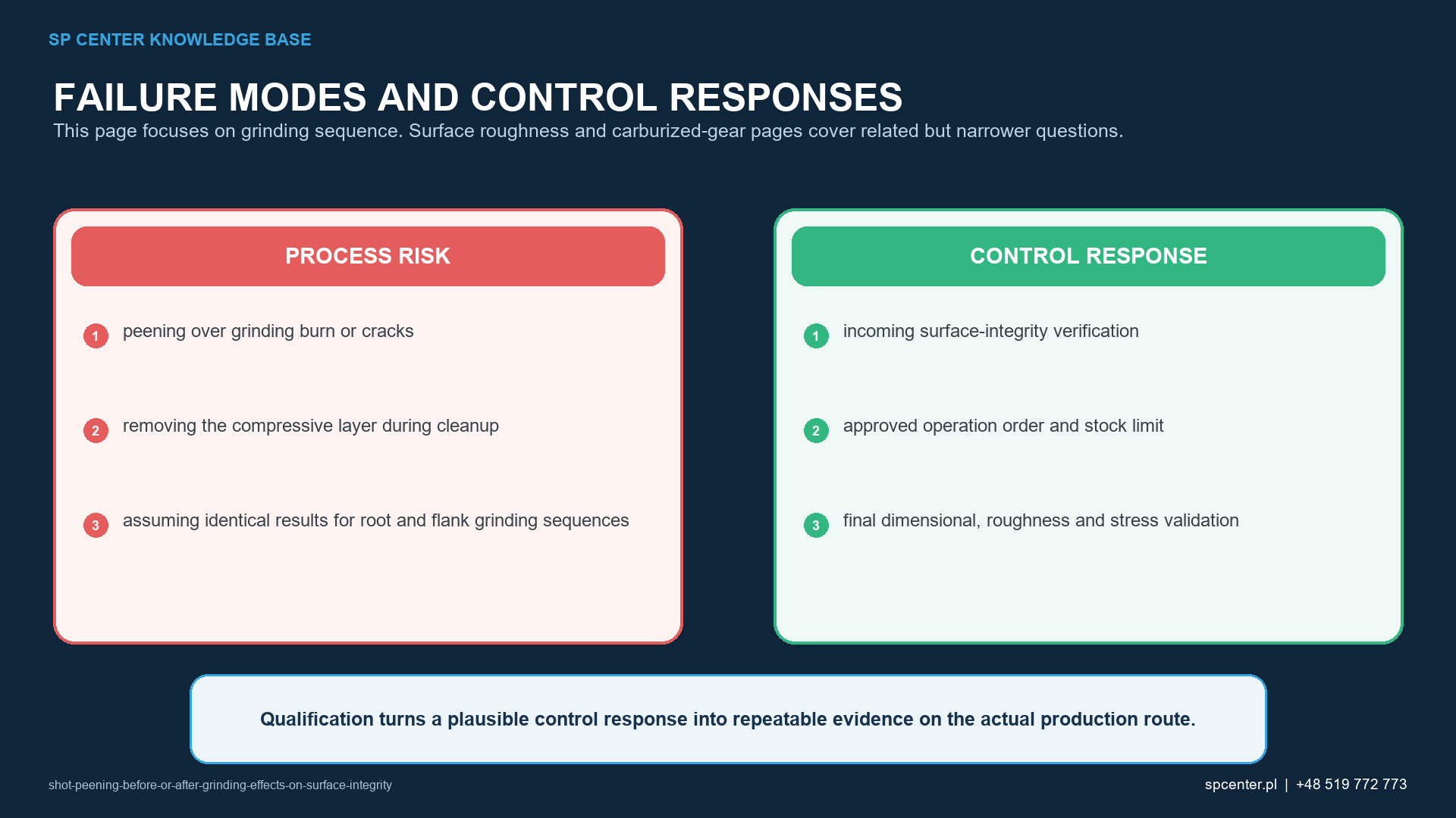
The control plan should address the failure modes relevant to the material and grinding operation. These can include burn, cracking, tempering or rehardened layers, smeared material, excessive roughness, dimensional error and unfavorable residual stress. The inspection method and acceptance limit come from the drawing, specification, approved manufacturing plan or customer decision; no single inspection is universally sufficient.
Shot peening is not a crack-repair method and must not be used to hide a rejectable surface. If the incoming condition is uncertain, stop processing, preserve traceability and obtain a controlled disposition before peening.
Which variables must remain fixed during qualification?
Qualification should use the actual material and heat-treatment condition, representative geometry and the production grinding and finishing route. For peening, it should include equipment, media type, size and condition, intensity and saturation method, flow, nozzle or wheel configuration, angle, stand-off, motion, fixture, masking, exposure, coverage method and cleaning.
The trial should challenge the hardest-to-reach feature and the most damage-sensitive or dimensionally critical surface. If stock removal follows peening, measure it with a method capable of resolving the specified limit rather than relying only on elapsed finishing time.
Which evidence is needed for production release?
| Evidence | What it establishes | What it cannot establish alone |
|---|---|---|
| Grinding-process and incoming inspection records | The surface entered peening in the specified condition | That peening preserved final roughness, dimensions or fatigue performance |
| Almen intensity and saturation curve | The peening stream was verified under defined test conditions | The amount of stock later removed or the final residual-stress profile |
| Component coverage | The specified surface shows the required impact evidence before any authorized removal | Absence of grinding burn, crack repair or retained fatigue benefit after finishing |
| Roughness and geometry | The final profile, dimensions and form meet the invoked limits | The magnitude and depth of compressive residual stress |
| Residual-stress measurement | A defined stress component at stated location, direction and depth | Universal transfer to another geometry, material or service load |
| Representative fatigue or functional test | The qualified route addresses a defined application claim | Compliance after an unreviewed sequence or stock-removal change |
Table 2. Stream control, surface acceptance and application performance remain separate evidence layers.
SAE J442 and J443 address tools and procedures for determining and verifying peening intensity, while J2277 addresses coverage determination. These controls do not by themselves define an allowable grinding amount. AS7045 provides a framework for residual-stress definition, quantification and classification, but the governing drawing and qualification plan still determine whether and how residual stress is an acceptance characteristic.
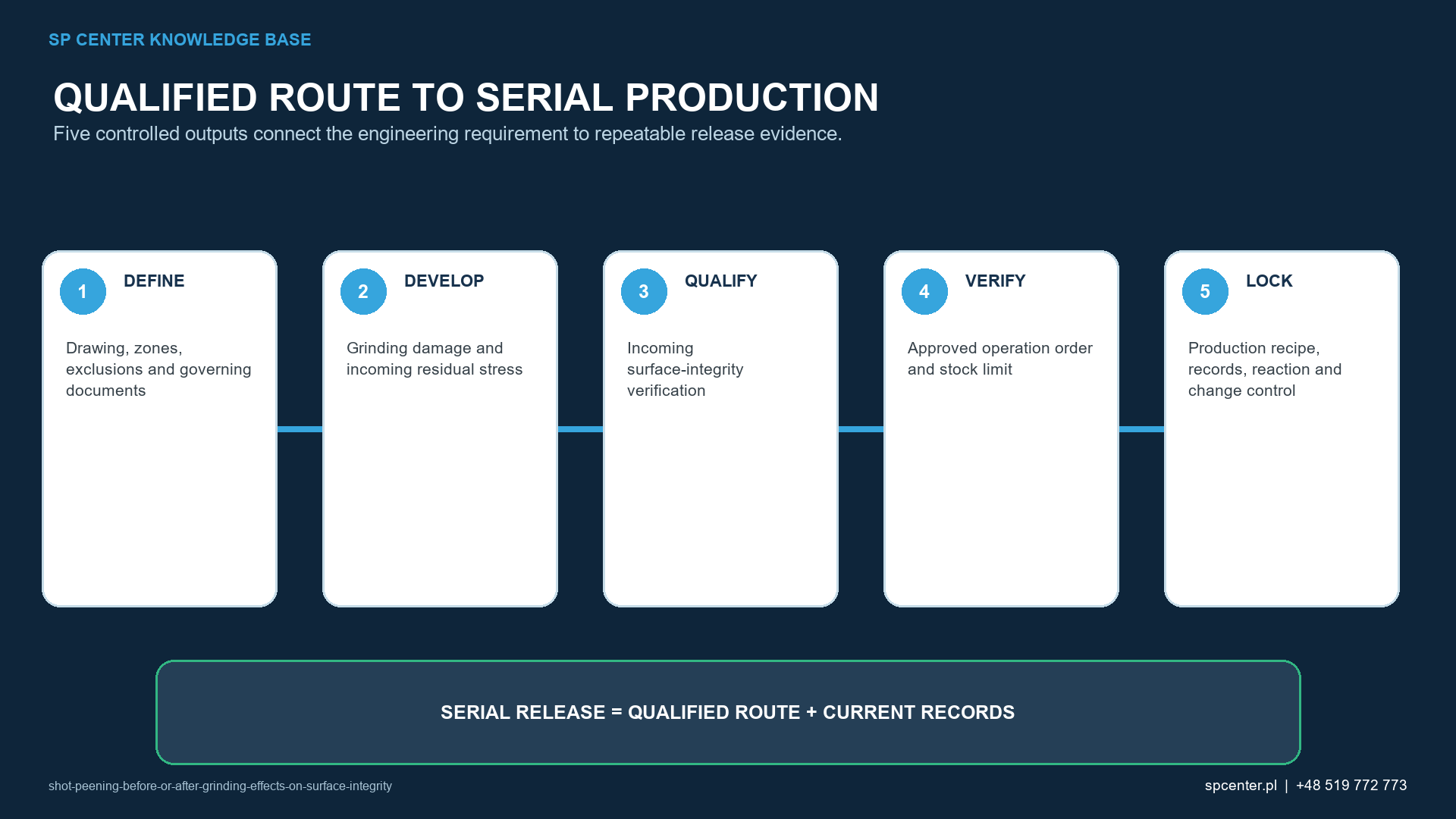
Which changes require review or requalification?
- Grinding wheel, dresser, coolant, feed, speed, depth or grinding direction changes in a way that can alter the incoming surface.
- A honing, lapping, polishing, superfinishing or blend step is added, removed or changed.
- The permitted stock-removal limit or measurement method changes.
- Material, heat treatment, case depth, hardness, geometry or treatment boundary changes.
- Peening equipment, media, fixture, program, motion, intensity range or coverage method changes outside the approved baseline.
- Final roughness, dimension, residual-stress or fatigue evidence no longer matches the qualified condition.
The response depends on the governing specification and customer flow-down. At minimum, the change should be assessed against the approved relationship between process inputs, the final surface and acceptance outputs before affected product is released.
What should an RFQ, drawing or process plan specify?
| RFQ or drawing input | Why it matters | Ambiguity prevented |
|---|---|---|
| Material and heat-treatment condition | Controls hardness, case condition and damage sensitivity | A route is copied between dissimilar metallurgical states |
| Grinding method and incoming condition | Defines the surface presented to peening | Peening is expected to hide burn, cracks or unacceptable tensile stress |
| Operation order and permitted stock removal | Determines whether the peened layer is preserved or modified | ‘Light polish’ becomes an uncontrolled manufacturing step |
| Treatment, exclusion and transition zones | Protects flanks, fits, seals and other functional surfaces | Overspray or masking shifts the approved boundary |
| Final roughness, dimensions, form and inspection | Creates component acceptance beyond stream settings | Intensity and coverage are treated as complete release evidence |
| Residual-stress or performance requirement | Links a specific claim to a qualified method | A generic fatigue benefit is promised without a validation basis |
Table 3. Sequence language must define the final accepted condition and not leave stock removal to interpretation.
Also identify part revision, datums, batch logic, cleaning and packaging, required records and the authority for deviations. Where requirements conflict or the permissible sequence is absent, pause processing and obtain controlled clarification rather than inventing an internal substitute.
Frequently asked questions
Should shot peening always be performed after grinding?
No. Peening after final grinding is common when later material removal must be avoided, but the correct order comes from the drawing, surface function, material condition and qualified route.
Can grinding be performed after shot peening?
Only when the approved route defines the finishing method and permissible removal and verifies the final surface, geometry and any retained application-specific effect.
Does shot peening repair grinding burn?
No. Grinding burn, cracks and other rejectable surface-integrity conditions require detection and disposition before peening. Peening must not be used to conceal them.
Is a light polish after peening harmless?
Not automatically. Even small removal can alter texture and the most affected near-surface region. The method, direction, allowance and acceptance evidence require control.
Does correct Almen intensity prove the final residual-stress profile?
No. Almen intensity verifies the peening stream under standardized conditions. Component residual stress depends on material, geometry, coverage, sequence and any later removal.
Should coverage be inspected before or after finishing?
Follow the governing requirement and qualified route. Coverage normally concerns peening impact evidence; a later finishing step can obscure that evidence and needs its own controlled acceptance.
Can residual-stress measurements define the permitted grinding allowance?
They can support qualification when the method, direction, depth and uncertainty are appropriate, but the allowance must also protect dimensions, texture and required component performance.
What information does SP Center need for a sequence review?
Provide the controlled drawing, material and heat treatment, grinding and finishing route, treatment map, specifications, surface and dimensional limits, quantities and required records.
Key takeaways
- There is no universal before-or-after rule; the final surface function and approved route decide.
- Accept grinding integrity before peening and do not treat peening as defect repair.
- Control every material-removal step after peening by method, limit and final evidence.
- Protect precision and functional surfaces with explicit treatment and exclusion zones.
- Keep Almen intensity, coverage, final geometry, residual stress and fatigue evidence distinct.
- Qualify the complete production route on representative material and geometry.
Related SP Center guides
- Shot Peening Before or After Heat Treatment
- Shot Peening and Coatings: Process Sequence
- Surface Roughness After Shot Peening
- XRD Residual Stress Measurement
Technical references
1. SAE J2441_202511: Shot Peening, stabilized November 2025
2. SAE AMS2430U: Shot Peening, revised April 2018
3. SAE ARP7488: Peening Design and Process Control Guidelines, issued January 2018
4. SAE J442_202602: Tools for Peening Intensity Determination and Verification, revised February 2026
5. SAE J443_202512: Procedures for Determining and Verifying Peening Intensity, revised December 2025
7. Sakurada and Kobayashi, Effects of Shot Peening and Grinding on Gear Strength, SAE 940729
Standards note: Use the complete revisions invoked by the drawing, contract and customer flow-down. The cited gear study is application-specific and is not a universal stock-removal or fatigue value.
Author: Paweł Kmieć
Discuss a grinding and shot peening sequence: +48 519 772 773 | [email protected]