


Present a known surface to the shot stream, preserve inspection evidence and remove media and residues without altering the peened result
Before shot peening, preparation must expose the authorised component surface without introducing damage or incompatible residue. After shot peening, cleaning must remove loose media and process residues without destroying required coverage evidence or altering the mechanically modified surface. These objectives belong to a controlled sequence: identify, prepare, inspect, mask/apply tracer, peen, verify, clean, protect and release.
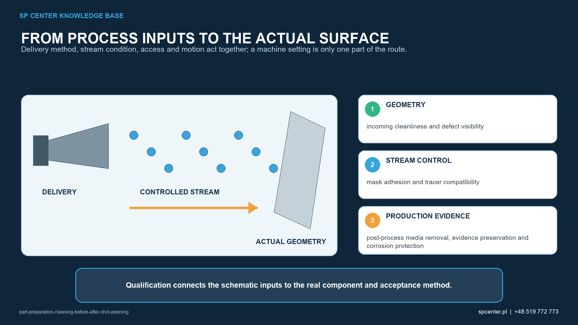
What must pre-peening preparation establish?
Correct media, intensity and machine settings cannot compensate for an unknown incoming surface. The objective is not merely a visually attractive part; it is a repeatable surface condition compatible with the drawing, component material, approved manufacturing route, masking, inspection and media system.
| Incoming condition | Process risk | Required disposition |
|---|---|---|
| Oil, grease or corrosion inhibitor | Mask/tracer adhesion failure, media contamination and uncertain particle–substrate contact | Use an approved material-compatible cleaning method; verify removal and drying |
| Scale, oxide or corrosion products | Inconsistent interaction and hidden surface damage | Remove only by a separately authorised operation and inspect the exposed surface |
| Chips, foreign grit or loose abrasive | Foreign particles enter the media/recovery system or damage later parts | Remove before loading; contain equipment if cross-contamination is suspected |
| Burr, scratch, gouge, lap, grinding burn or damaged thread | The defect remains on a fatigue-relevant surface after peening | Inspect and obtain authorised disposition; do not use peening to hide a nonconformance |
| Retained liquid or moisture | Corrosion, tracer/mask failure and media-system contamination | Drain and dry the complete geometry by an approved, verified route |
Table 1. Incoming cleanliness and surface integrity are different but coordinated acceptance questions.
Why are shot peening and blast cleaning separate processes?
Shot peening is a controlled surface-enhancement process. Blast cleaning or shot blasting is a mechanical pre-treatment intended primarily to clean or abrade, for example by removing scale or contamination. A peening cycle should not be expected to degrease a part, remove heavy corrosion or replace an approved descaling process.
When blast cleaning is required before peening, define its media, equipment, surface effect, acceptance and contamination controls as a separate operation. The downstream peening qualification must use the authorised incoming condition that this operation creates.
How is a cleaning method approved for the component?
| Cleaning approval question | Why it matters | Evidence |
|---|---|---|
| Can the method attack the alloy, case or coating? | A cleaner acceptable for one material may damage aluminium, titanium, magnesium, stainless steel or a coating | Material/process compatibility and authorised limits |
| Can it change dimensions or surface integrity? | Aggressive chemical or mechanical action can alter critical geometry or introduce defects | Qualified parameters and required surface/dimensional inspection |
| Does it leave residue? | A dry-looking film can affect masks, tracers, media and downstream operations | Cleanliness method and acceptance criteria |
| Can liquid remain in internal features? | Retained solution can transport contamination or promote corrosion | Drainage/drying route and risk-based verification |
| Can handling recontaminate the surface? | Hands, gloves, fixtures, tables, containers and lifting tools can undo cleaning | Controlled handling, tool cleanliness, hold time and storage |
Table 2. Cleaning suitability depends on material, geometry, surface condition and the complete manufacturing sequence.
Machining, deburring, grinding, heat treatment, inspection and cleaning can precede peening, but their order is application-specific. Machining or blending after peening can remove part of the affected layer and must not be introduced without engineering authorisation.
How is the prepared condition preserved?
A clean part can be recontaminated by bare hands, dirty gloves, worktables, transport containers, fixtures, lifting tools or masks. Tooling cleanliness, maximum hold time where applicable, controlled storage and transfer into the machine are part of preparation.
Masks require clean seating or adhesion surfaces. A coverage tracer is different: it is an intentional inspection material applied by an approved method. The substrate must support a uniform, reliable tracer film, and the tracer must remain until coverage inspection is complete.
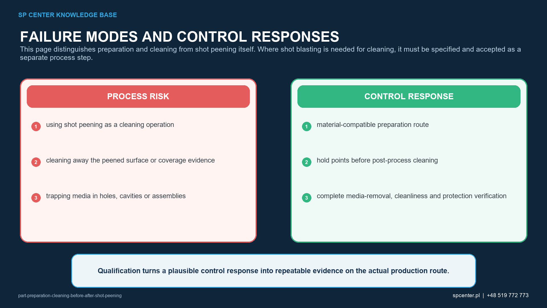
Why must coverage evidence be preserved before cleaning?
Visual or fluorescent evidence must remain available long enough to evaluate treated areas, shadowed regions, boundaries and incomplete coverage. The qualified sequence should state: peen, inspect coverage, record the result, then remove tracer and other residues as required.
Almen intensity characterises the standardised stream response. It does not prove incoming cleanliness, correct masking, component coverage or removal of loose media.
How is loose media removed from the complete component?
| Feature or residue | Removal/verification concern | Controlled response |
|---|---|---|
| External surfaces and open threads | Loose particles remain in local geometry | Approved air, vacuum, washing or orientation method without damaging the surface |
| Blind holes and deep cavities | Particles cannot drain by gravity or be seen directly | Defined orientation, extraction/cleaning method and verification appropriate to risk |
| Cross-holes and connected channels | Particles migrate between features | Evaluate the complete path and both entry/exit directions |
| Masks, tape and adhesive | Residue, tool marks or trapped media remain after removal | Controlled removal followed by protected- and boundary-surface inspection |
| Coverage tracer | Removed before inspection or retained when downstream cleanliness prohibits it | Inspect and record first; then use the approved tracer-removal route |
| Dust and fractured media | Can remain in rough surfaces, grooves or assemblies | Risk-based cleanliness check and containment of any affected process system |
Table 3. Post-peening cleaning follows geometry, residue type and a risk-appropriate verification method.
A trapped particle can block lubrication, interfere with assembly or become foreign-object debris. The plan must explain how media can enter each feature, how it will be removed and how the result will be verified—not merely how the visible exterior will be blown off.
How can cleaning damage the peened surface?
The peened texture is not a defect by itself. Unapproved grinding, blending, abrasive polishing or aggressive chemical action can remove or alter the mechanically modified surface. Where passivation, plating, coating or another treatment follows, its sequence and permissible material removal must come from engineering documentation.
What does final release require?
| Stage | Primary objective | Do not confuse with |
|---|---|---|
| Before peening | Expose the authorised substrate, reveal defects and protect the qualified media system | Cosmetic cleaning or reliance on the peening stream to remove contamination |
| After peening, before coverage release | Preserve evidence required to assess treatment, boundaries and shadowed regions | Immediate washing that destroys tracer or other required evidence |
| After coverage release | Remove loose media, masks, tracer and residues without altering the result | Grinding, blending, abrasive polishing or aggressive chemical attack unless authorised |
| After final cleaning | Verify cleanliness, protect the surface and identify downstream route status | Uncontrolled handling, corrosion inhibitor, storage or packaging |
| Before downstream coating or assembly | Confirm compatibility, dryness, media-free condition and required records | Assuming that visual cleanliness proves functional cleanliness |
Table 4. The word cleaning covers distinct objectives before and after the peening operation.
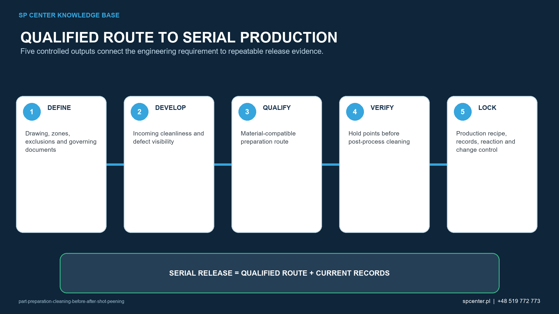
- No loose media in external or internal features.
- No prohibited cleaner, tracer, adhesive or other process residue.
- Coverage already inspected and documented by the approved method.
- Acceptable masking boundaries and protected surfaces.
- Undamaged threads, datums, seals, fits and other functional features.
- Required surface, dimensions, corrosion protection, packaging and downstream status accepted.
Why must parts be cleaned before shot peening?
The peening stream must reach a known, authorised surface. Oil, scale, corrosion, chips and foreign abrasive can affect masking, coverage inspection, media cleanliness and particle–substrate interaction or hide defects.
Is shot peening also a cleaning process?
No. Its primary purpose is controlled surface enhancement. Blast cleaning or shot blasting is a separate process step whose media, equipment, acceptance and contamination controls must be authorised independently.
Can shot blasting be used before shot peening?
Yes, when the material, drawing and approved manufacturing route permit a separately controlled blast-cleaning step. Its purpose, surface change, contamination risk and acceptance must be defined before the subsequent peening operation.
When should fluorescent coverage tracer be removed?
Only after the required coverage inspection and documentation. The approved process sequence must preserve the evidence long enough to assess treated, shadowed and boundary areas.
How is loose media removed from blind holes and channels?
Use a qualified orientation, air, vacuum, wash or extraction route compatible with the part. The method and verification must address the complete internal path and service risk, not only the visible exterior.
Can a peened surface be polished after cleaning?
Only when the drawing and authorised route define the operation and permissible material removal. Unapproved grinding, blending or aggressive polishing can remove or alter the mechanically modified layer.
Does correct Almen intensity prove part preparation and cleaning are acceptable?
No. Almen intensity verifies standardised stream response. Incoming cleanliness, defect disposition, masking/tracer condition, component coverage, loose-media removal and final cleanliness require separate evidence.
What should an RFQ include?
Provide the drawing and revision, material and heat treatment, incoming condition, prior and subsequent operations, treatment/exclusion zones, specifications, intensity/coverage, internal geometry, cleanliness, corrosion-protection, packaging and record requirements.
Key takeaways
- Create a defined surface condition before peening.
- Treat degreasing, descaling and blast cleaning as separate controlled operations.
- Keep parts, masks, fixtures, handling tools and containers clean.
- Preserve coverage evidence until inspection and documentation are complete.
- Remove loose media from the complete geometry, including internal passages.
- Do not abrade or chemically attack the peened layer without engineering authority.
- Protect the cleaned peened surface until the next controlled operation.
Related SP Center guides
Technical sources
1. SAE AMS2430U: Shot Peening, revised April 2018
2. SAE J792_202209, SAE Manual on Blast Cleaning
3. SAE J2277_202301: Shot Peening Coverage Determination, revised January 2023
4. SAE ARP7488: Peening Design and Process Control Guidelines, issued January 2018
5. SAE J2441_202511: Shot Peening, stabilized November 2025
6. SAE J443_202512: Procedures for Determining and Verifying Peening Intensity, revised December 2025
Standards note: The complete drawing, process specifications, customer flow-down and approved cleaning route control the component. This guide does not prescribe a universal cleaner, cleanliness limit or media-removal method.
Author: Paweł Kmieć
Discuss preparation, cleaning and shot peening sequence: +48 519 772 773 | [email protected]