


Compare media acceleration, chamber and access constraints, Almen evidence, coverage, media control, qualification and serial production
Conventional and ultrasonically activated shot peening both use solid media impacts, but the media are accelerated in different ways. Conventional equipment directs an air-blast or centrifugal-wheel stream toward the component. An ultrasonic system excites shot within a bounded treatment chamber through a vibrating sonotrode. These routes have different equipment configurations, access patterns, monitored inputs and qualification evidence; neither may replace the other without technical and contractual authorization.
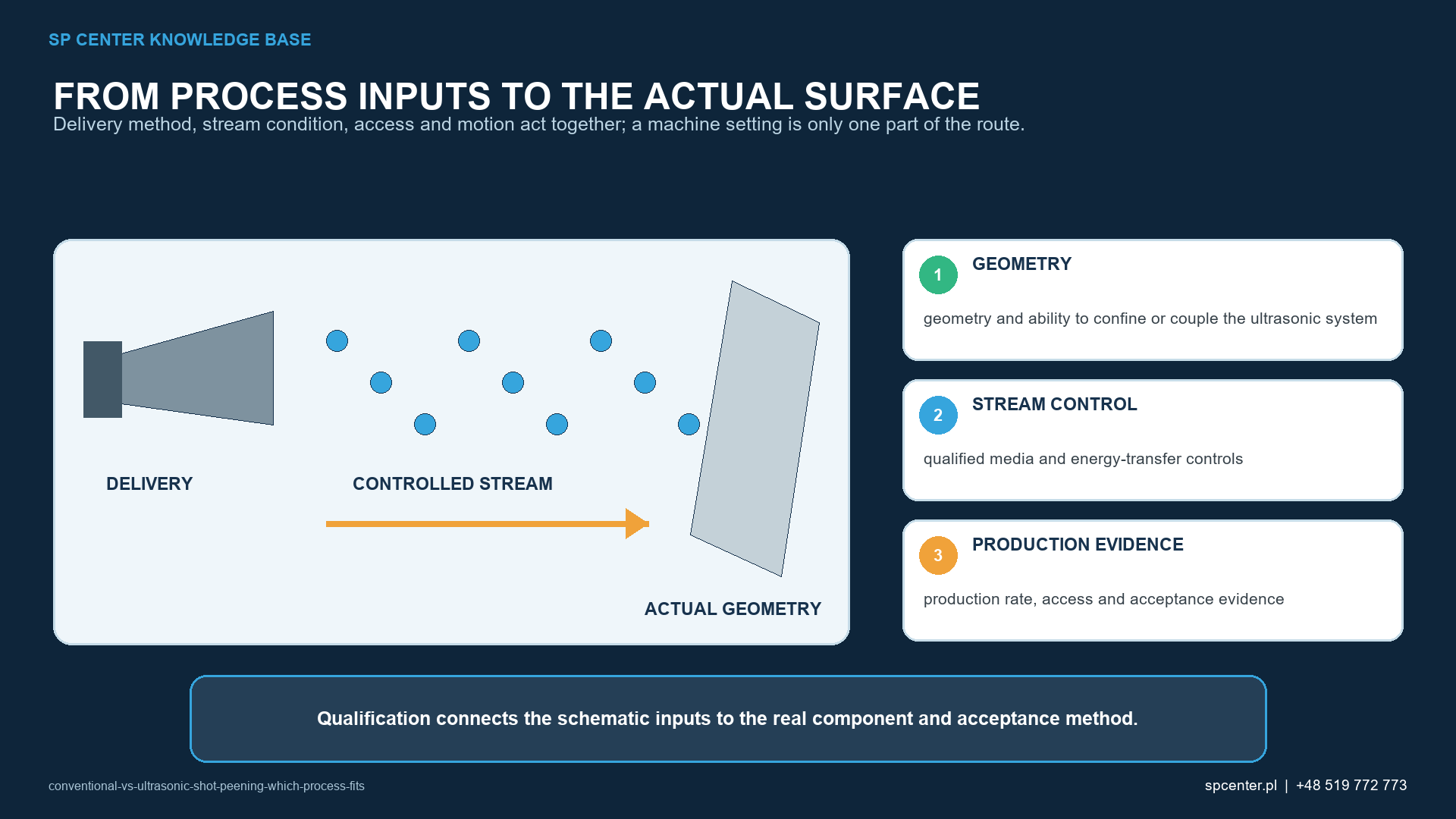
How do the two processes accelerate the shot?
In air-blast shot peening, compressed air and a nozzle accelerate the medium. In wheel shot peening, a controlled wheel supplies the kinetic energy. Nozzle or wheel geometry, media flow, distance, angle, part motion, exposure and rebound define the stream presented to the surface.
In ultrasonically activated shot peening, an ultrasonic generator, transducer and sonotrode create high-frequency vibration. The sonotrode transfers energy to loose shot confined near the part. The shot follows repeated trajectories between the sonotrode, chamber surfaces and component. Chamber geometry, reflector or cover, shot population, part position and treatment time therefore become integral parts of the process.
| Comparison area | Conventional shot peening | Ultrasonically activated shot peening |
|---|---|---|
| How shot is accelerated | Compressed air through a nozzle or a centrifugal wheel creates a directed stream | An ultrasonically driven sonotrode transfers energy to shot contained by the treatment chamber |
| Shot trajectories | Predominantly set by nozzle or wheel stream, part motion and rebound | Repeated and partly stochastic within the chamber, influenced by chamber, reflector, part and shot population |
| Typical process inputs | Pressure or wheel speed, media flow, nozzle or wheel geometry, distance, angle, motion and exposure | Frequency and amplitude under the qualified system, sonotrode and chamber configuration, shot identity and quantity, part position and treatment duration |
| Access strategy | Direct nozzle, lance or wheel exposure with controlled shadowing and rebound | A closed or bounded treatment volume that allows activated shot to reach the qualified surfaces |
| Media control | Type, size, hardness, shape, contamination, breakdown and operating mix | Type, size, hardness, shape, quantity, contamination, wear and movement within the qualified chamber |
| Acceptance | Required intensity, coverage, surface, dimensions and records under the invoked specification | Requirements and evidence defined by AMS2580A or another invoked ultrasonic-peening route, drawing and customer flow-down |
Table 1. The medium can look similar, but its acceleration, trajectory and process configuration are different.
How is ultrasonic shot peening different from ultrasonic impact treatment?
The terms are sometimes mixed, which can produce an incorrect purchase or qualification route. Ultrasonically activated shot peening uses loose shot particles. Ultrasonic impact treatment, ultrasonic peening treatment and similar tool-based methods can use pins, needles or rods coupled to a sonotrode and directly applied to the surface, often along weld toes or localized paths.
Both families can plastically deform metal, but their contact mechanics, tooling, treated footprint, media or pin control and standards basis are not automatically equivalent. The controlled drawing, process specification and supplier approval should state the exact technology.
Which process can reach complex geometry?
A conventional air-blast system can direct a nozzle or lance toward an internal radius, bore or cavity. Reach depends on nozzle size, line of sight, stand-off, angle, rebound, masking, media flow and the ability to remove shot. A wheel has a broader stream and can suit accessible production geometries, but is not interchangeable with a nozzle for every feature.
An ultrasonic chamber can create impacts from multiple directions and can be useful for localized or enclosed treatment volumes. That does not eliminate access risk. The part can shield itself, the fixture can create dead zones, shot can collect away from a feature, and a tight channel can trap media. Chamber closure and recovery after treatment are safety and quality functions, not housekeeping details.
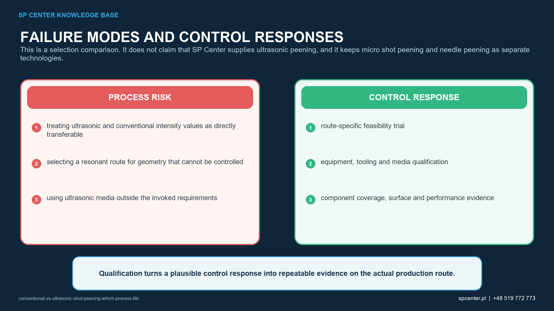
Which variables must be controlled?
| Engineering question | Conventional route consideration | Ultrasonic route consideration |
|---|---|---|
| Can every required zone be reached? | Demonstrate stream angle, stand-off, nozzle or wheel path, shadowing and rebound | Demonstrate chamber access, shot circulation, dead zones, part support and closure |
| Can excluded features be protected? | Qualify masks, plugs, transitions and resistance to the directed stream | Qualify masks, plugs and seals for repeated impacts from multiple directions |
| Can the shot be removed? | Control cavities, bores and orientation after the directed exposure | Control chamber opening, part extraction, internal features and complete shot recovery |
| Can intensity be verified? | Use the complete Almen range, strip and holder arrangement required by the governing route | Use only the intensity method and test arrangement defined by the governing ultrasonic specification and qualified configuration |
| Can coverage be accepted? | Inspect every required zone under the approved method and conditions | Demonstrate that repeated chamber impacts reach every required zone and apply the approved route-specific method |
| Can production be reproduced? | Lock equipment, media, fixture, motion, exposure and monitored input ranges | Lock generator, transducer, sonotrode, chamber, shot population, part presentation, duration and monitored input ranges |
Table 2. Access and verification must be demonstrated for the chosen route rather than inferred from the process name.
For a conventional process, pressure or wheel speed is only one input. Media flow and condition, nozzle or wheel geometry, motion, exposure and the complete Almen setup remain necessary controls. A conforming pressure reading does not prove intensity or coverage.
For an ultrasonic process, nominal generator frequency alone is equally insufficient. Transducer and sonotrode identity, amplitude or another specified output measure, chamber geometry, interfaces, shot identity and charge, part loading and duration can influence the impact population. The qualified equipment must define which values are monitored and how an interruption is detected.
How should intensity be specified and verified?
For conventional shot peening, the complete Almen intensity range and strip designation should be stated by the controlling document or formally proposed and approved. A saturation curve determines intensity under the specified holder arrangement; one arbitrary exposure or one pressure value is not a substitute.
SAE describes AMS2580A as covering the use of ultrasonically activated shot peening to induce compressive residual stress on metal-part surfaces. Its complete revision must be used to establish the applicable intensity method, test piece or strip arrangement and frequency of verification. Do not reuse a conventional holder, correlation or machine setting merely because both routes use shot.
How is coverage demonstrated?
Coverage concerns the required component surface, not the Almen strip. In a conventional directed stream, the exposure path and part motion must reach all treatment zones without mask leakage or shadowing. In an ultrasonic chamber, repeated random or semi-random trajectories must still reach every specified zone.
Lighting, magnification, surface condition, inspection orientation and the acceptance threshold must be defined by the approved route. Fluorescent or other indirect techniques require qualification and correlation when used. Extra duration cannot be assumed to repair an inaccessible zone and may increase roughness, distortion or surface damage elsewhere.
How do surface roughness and residual stress compare?
Both processes can change roughness, hardness, cold work and residual stress. Their outcome depends on the material and starting condition, shot size, hardness and shape, impact energy, exposure, geometry and later operations. Experimental ultrasonic-shot-peening studies show that shot motion and treatment parameters can affect roughness and residual-stress response, but results for one alloy and specimen cannot be generalized to another component.
Neither the word ultrasonic nor a high operating frequency guarantees a deeper, smoother or more fatigue-resistant surface. The required outcome should be validated on representative material and geometry through surface, dimensional, residual-stress or fatigue evidence as invoked by the design authority.
Can one route be transferred to another machine or part?
No recipe is portable by default. A conventional process depends on equipment, nozzle or wheel, media circuit, fixture, motion and working envelope. An ultrasonic route depends on generator, transducer, sonotrode, chamber, shot population, part support and interfaces. A change that alters impact energy, distribution, access or acceptance can require requalification.
Geometric similarity alone is insufficient. A new part can introduce a dead zone, rebound path, altered chamber volume, different media recovery or a surface whose incoming condition responds differently.
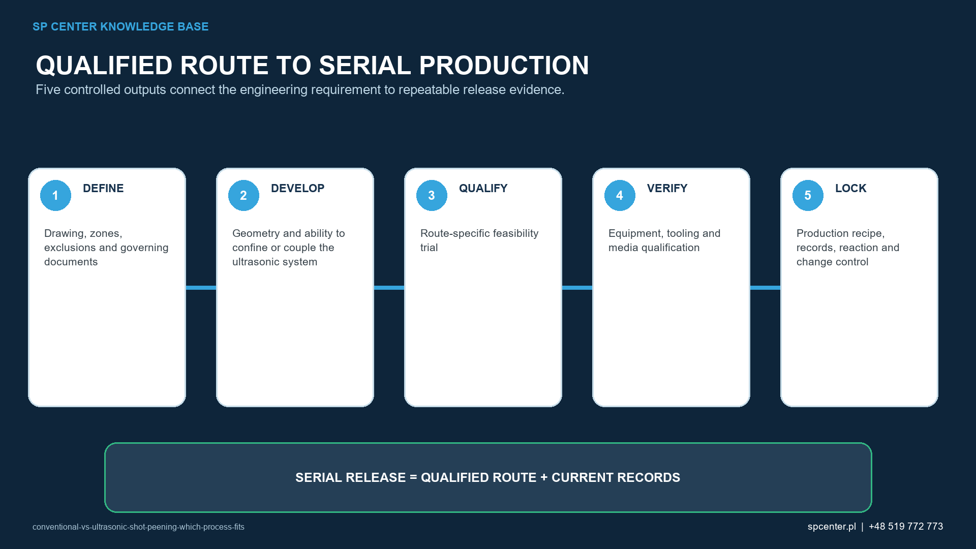
What should be recorded in production?
| Control stage | Evidence to retain | Reason to stop or contain work |
|---|---|---|
| Requirement review | Drawing, revision, process identity, zones, exclusions, media, intensity, coverage, surface and approval hierarchy | Process type is ambiguous, specification is missing or requirements conflict |
| Equipment configuration | Machine, generator where applicable, nozzle or wheel or sonotrode, chamber, fixture, masks, program and revision | Unapproved hardware, damaged sonotrode or mask, wrong chamber or uncontrolled software |
| Media | Batch, specification, size, hardness, shape, contamination, operating condition and quantity where relevant | Wrong medium, excessive breakdown, contamination or unverified chamber charge |
| Process verification | Required saturation, intensity, coverage and representative access evidence | Failed verification, changed test arrangement or inaccessible treatment zone |
| Execution | Part identity, loading, position, exposure, monitored values, alarm and interruption status | Loss of motion, ultrasonic output, media delivery or traceability |
| Release | Surface, boundary, damage, cleanliness, dimensions, retained-media and customer records as invoked | Uncovered area, trapped media, open nonconformance or incomplete evidence |
Table 3. Release requires evidence for the actual part, approved configuration and complete treatment cycle.
What information belongs in an RFQ?
- Controlled drawing, revision, part identity and specification hierarchy.
- Explicit process name: conventional air-blast or wheel shot peening, or ultrasonically activated shot peening.
- Material, heat treatment, hardness, prior operations and incoming surface.
- Treatment, exclusion and transition zones plus internal features and media-removal requirements.
- Complete intensity requirement and test arrangement, coverage and media limits under the governing route.
- Surface, damage, roughness, dimensional, cleanliness and retained-media criteria.
- Qualification, source approval, first-article, record and change-control requirements.
- Part size, mass, lot pattern, annual demand, packaging and target date.
Frequently asked questions
What is ultrasonically activated shot peening?
It is a shot peening process in which an ultrasonic system transfers vibration through a sonotrode to shot contained in a treatment chamber. Repeated shot impacts plastically strain the surface and can induce compressive residual stress under a qualified route.
Is ultrasonic shot peening the same as ultrasonic impact treatment?
No. Ultrasonic impact treatment commonly uses pins or needles driven by an ultrasonic tool in direct contact with the workpiece. Ultrasonically activated shot peening uses loose shot. The drawing and specification must identify the intended process.
Is ultrasonic shot peening better for every internal feature?
No. A chamber can support multi-directional impacts, but dead zones, tight passages, masks, part support and media recovery can remain limiting. Access must be qualified on the actual or representative geometry.
Does ultrasonic shot peening use Almen intensity?
Use only the intensity definition, strip and test arrangement required by the governing ultrasonic specification. A conventional holder or machine correlation must not be transferred without technical authority and qualification.
Does a chamber treatment guarantee full coverage?
No. Shot motion can be affected by part geometry, shot quantity, sonotrode condition, chamber walls, masks and duration. Coverage must be demonstrated in every required zone with the approved method.
Can the same media specification be used in both processes?
Only when the governing documents permit it and the complete medium is suitable for the qualified equipment. Media type, size, hardness, shape, quantity and operating condition remain process variables.
Can conventional shot peening be replaced by ultrasonic shot peening?
Not without formal authorization. AMS2430 or AMS2432 and AMS2580A describe different routes. A change requires review of the drawing, source approval, qualification, component evidence and customer requirements.
Does SP Center offer ultrasonically activated shot peening?
SP Center specializes in conventional shot peening. We can review requirements and feasibility for our conventional process; this article does not represent an offer of ultrasonic shot peening services.
Key takeaways
- Both routes use shot, but they accelerate and distribute it differently.
- Ultrasonically activated shot peening is not the same as direct-pin ultrasonic impact treatment.
- Chamber, sonotrode, shot charge and part presentation are qualified process configuration.
- Almen and coverage evidence must follow the selected governing route.
- Neither a pressure value nor an ultrasonic frequency proves the component result alone.
- Substitution or transfer requires formal review and application-specific evidence.
Related SP Center guides
Technical references
1. SAE AMS2580A, Shot Peening, Ultrasonically Activated
2. SAE AMS2430U: Shot Peening, revised April 2018
3. SAE AMS2432E: Shot Peening, Computer Monitored, revised October 2022
4. SAE J442_202602: Tools for Peening Intensity Determination and Verification, revised February 2026
5. SAE J443_202512: Procedures for Determining and Verifying Peening Intensity, revised December 2025
6. SAE J2277_202301: Shot Peening Coverage Determination, revised January 2023
Standards note: The complete revisions, drawing, approved route and customer-specific requirements invoked by the contract govern.
Author: Paweł Kmieć
Discuss a conventional shot peening requirement: +48 519 772 773 | [email protected]