


How visual assessment, tracer methods and digital image analysis can support defensible component-surface acceptance
Shot peening coverage is the extent to which the specified component surface has been impacted by the peening media. At 100% coverage, the required area is fully covered by impacts with no visible untreated regions when evaluated by the approved method and viewing conditions. Coverage is not Almen intensity, exposure time, surface damage or a coating percentage. Reliable inspection begins by separating the component-surface question from verification of the peening stream.
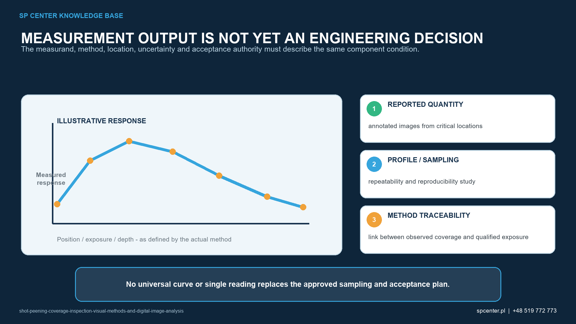
What question must coverage inspection answer?
The inspection must determine whether the complete drawing-defined treatment zone has received the required impact coverage and whether boundaries, exclusions and sensitive features remain acceptable. The method must be capable of resolving untreated islands, masked transitions and difficult geometry under the actual surface condition. A result taken on an easy flat area cannot automatically release a fillet, bore, root, edge or shielded feature.
The governing drawing, process specification and customer supplement define the coverage requirement and permitted evaluation route. SAE J2277 addresses shot peening coverage determination, but detailed application must follow the revision invoked for the work. This guide does not invent a universal magnification, lighting value or numerical image threshold.
Which inspection methods are available?
| Method family | Useful role | Primary limitation |
|---|---|---|
| Direct visual or magnified inspection | Assessment of impact coverage on accessible component surfaces using the invoked viewing conditions | Sensitive to lighting, surface finish, observer access and closely spaced impacts |
| Fluorescent or tracer-based method | Indirect indication of untreated or insufficiently impacted areas on complex geometry | Requires approved material, application, interpretation and correlation; indication is not the impact pattern itself |
| Digital image analysis | Repeatable image capture, segmentation and quantified comparison where a method is qualified | Algorithm and threshold can misclassify glare, contamination, roughness or overlapping impressions |
| Witness coupon or representative sample | Development, correlation or monitoring aid when permitted | Does not automatically prove the complete drawing-defined component surface |
Table 1. Method selection depends on the component, surface, geometry and contractual requirements. Indirect and digital methods are not automatically acceptable simply because they are convenient.
How should direct visual inspection be controlled?
- Confirm the treatment boundary, exclusion zones, required coverage and invoked inspection method.
- Verify that the component surface is in the condition for which the method is approved: clean, accessible and free from masking or contamination that obscures impacts.
- Use the specified viewing conditions, including applicable lighting, magnification and orientation.
- Inspect the entire required area systematically, including transitions, radii, bores, edges and regions affected by shadowing.
- Record the result and any uncertain area; do not infer acceptance from machine settings or nearby features.
- Escalate ambiguous indications through the controlled disposition route before release.
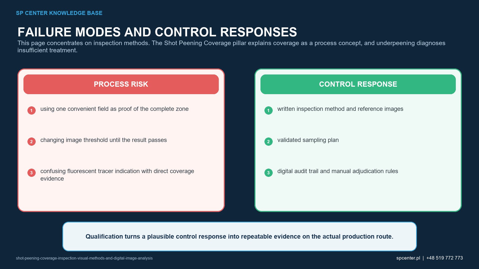
Why do lighting and surface condition matter?
Impact impressions are identified through changes in reflection, texture and local topography. Directional glare can hide impressions, while shadows can mimic untreated areas. Oxide, coating, dirt, embedded media, prior blasting or a very rough incoming surface can reduce contrast or create false features. The inspection procedure must therefore define a repeatable viewing arrangement and the range of surface conditions for which it is valid.
When the actual surface falls outside the qualified range, the answer is not to lower the acceptance threshold. The component should be held while the inspection route, cleaning allowance and customer requirements are reviewed.
How should a digital image-analysis method be qualified?
| Control dimension | What must be fixed | Evidence |
|---|---|---|
| Inspection boundary | Treatment zone, exclusion zone, transition and inaccessible features | Controlled drawing or inspection map |
| Image acquisition | Lighting direction and stability, magnification, focus, scale, camera position and surface preparation | Approved work instruction and image record |
| Analysis | Region of interest, algorithm version, thresholds, artefact handling and reviewer override | Qualified software configuration and audit trail |
| Acceptance | Definition of full coverage, treatment of ambiguous areas and escalation route | Customer-approved acceptance criteria and disposition record |
Table 2. A qualified digital route controls both the optical measurement and the interpretation. A percentage displayed by software is not meaningful without the configuration and correlation behind it.
Qualification should include representative materials, finishes, impact patterns, geometry and expected artefacts. Results should be compared with the approved reference method and reviewed for false positive and false negative classifications. Software or camera changes, altered lighting, new thresholds or a different surface family require change control and, where applicable, requalification.
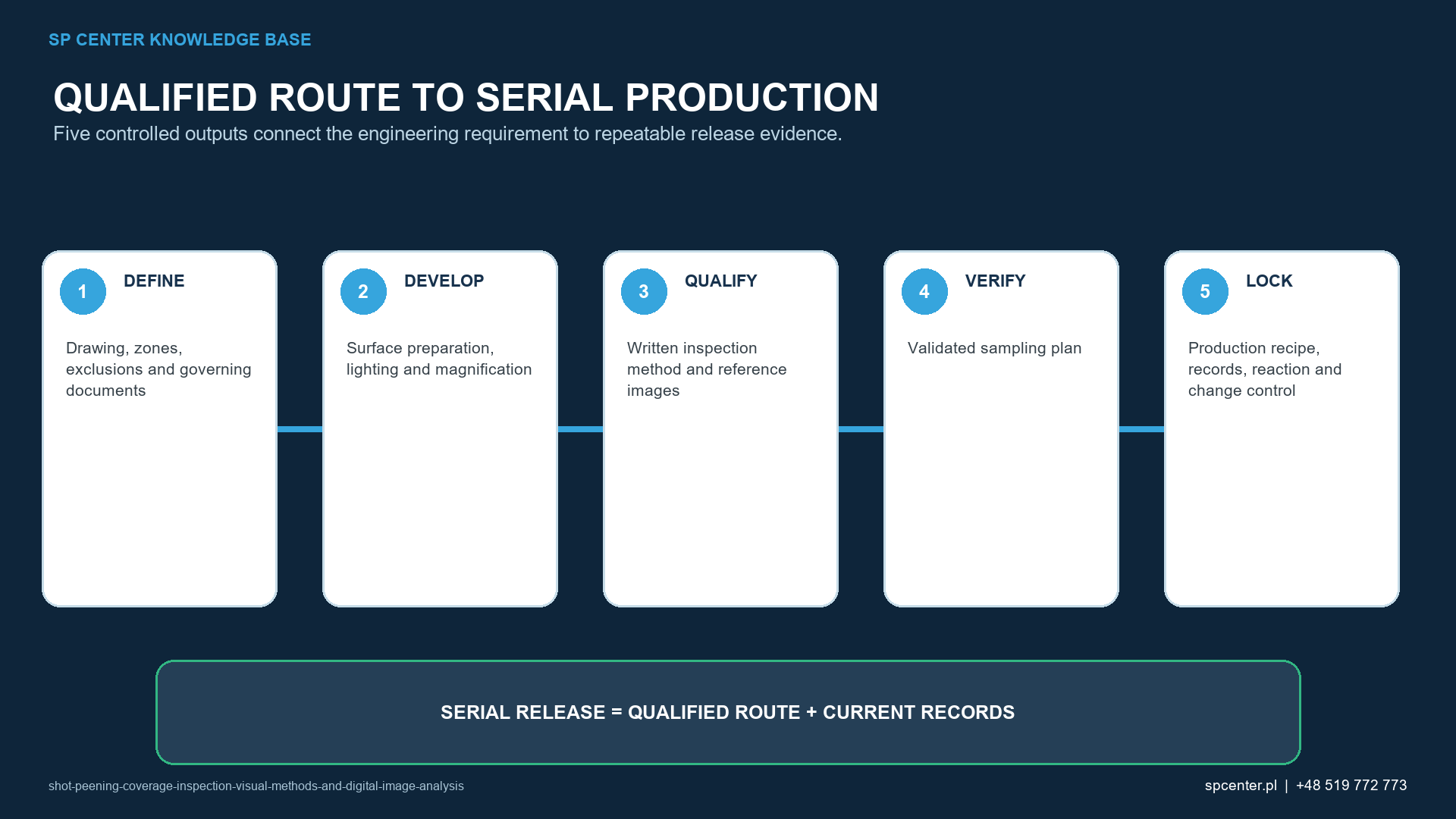
How should fluorescent or tracer methods be treated?
Tracer systems can make untreated regions easier to identify, especially on complex geometry, but they are indirect. Application thickness, drying or curing, illumination, viewing angle, contamination and removal can affect the indication. The complete method therefore needs approval and qualification, including correlation to the applicable coverage acceptance method and controls preventing an unacceptable effect on the component or downstream operations.
Which observations require a repeated inspection or technical review?
| Observed condition | Do not assume | Required action |
|---|---|---|
| Glare or shadow hides the impact pattern | That a dark or bright region is untreated | Reposition lighting or component and repeat inspection under the approved conditions |
| Surface is rough, coated, contaminated or previously blasted | That texture alone proves shot peening coverage | Use the qualified method and obtain technical review if the surface is outside its validated condition |
| Digital result changes after threshold adjustment | That the most favourable setting is acceptable | Restore the approved configuration and document investigation of the instability |
| Coverage is uncertain in a fillet, bore or masked boundary | That a conforming Almen result proves treatment | Inspect by the approved feature-specific route or hold for controlled disposition |
Table 3. Re-peening is not an automatic response to an uncertain indication. Cumulative exposure, surface condition, dimensions and the governing repair or rework rules must be reviewed first.
Which records support traceable acceptance?
- Part number, drawing and revision, treatment and exclusion zones.
- Invoked coverage requirement, inspection procedure and applicable method revision.
- Surface condition, lighting, magnification, orientation and equipment identification.
- Images or tracer records where required, including scale and inspected region.
- Software version, analysis configuration, thresholds, reviewer and any manual intervention.
- Result, ambiguous indications, repeated inspection, deviation and final disposition.
Frequently asked questions
What does 100% shot peening coverage mean?
It means complete impact coverage of the required surface with no visible untreated areas when evaluated by the approved method and viewing conditions. Detailed acceptance follows the invoked specification and customer requirements.
Does 200% coverage mean twice as many visible dents?
Not normally. Where the governing requirement defines 200% by exposure time, it means a total exposure equal to twice the time needed to achieve 100% coverage. The invoked document remains authoritative.
Can Almen intensity be used to accept component coverage?
No. Almen intensity verifies the peening stream under defined reference conditions. Coverage is a component-surface characteristic and requires a separate approved inspection.
Is digital image analysis automatically more objective?
No. It can improve repeatability only when image acquisition, software version, thresholds, artefact handling and reviewer actions are controlled and the method is qualified for the relevant surface.
Are fluorescent tracers direct coverage measurements?
They are indirect aids. Their use requires approval, qualification and correlation to the applicable coverage method for the process and component.
What should happen when coverage is uncertain?
Do not infer acceptance from intensity, cycle time or a nearby surface. Repeat or escalate the inspection under the approved procedure and hold the affected component until disposition.
Key takeaways
- Coverage answers whether the required component surface has been impacted; intensity verifies the peening stream.
- 100% coverage means complete coverage with no visible untreated areas under the approved assessment method.
- Lighting, access and surface condition can dominate the reliability of visual inspection.
- Digital and tracer methods require approval, qualification and correlation; they are not automatically superior or direct.
- Ambiguous coverage requires controlled reinspection or disposition, not inference from Almen results or cycle time.
Related SP Center guides
Technical references
1. SAE J2277_202301: Shot Peening Coverage Determination, revised January 2023
2. SAE AMS2430U: Shot Peening, revised April 2018
3. SAE ARP7488: Peening Design and Process Control Guidelines, issued January 2018
Standards note: The drawing, contract, customer requirements and revisions invoked for the programme remain authoritative.
Author: Paweł Kmieć
Discuss your shot peening requirement: +48 519 772 773 | [email protected]