


What the two requirements mean, how exposure is established and what must be verified in production
In controlled shot peening, 100% coverage is the point at which no unpeened areas are detectable on the specified surface under the approved inspection method and conditions. A 200% coverage requirement normally means that the part receives a total exposure time equal to twice the established time needed to reach initial 100% coverage, while the qualified process conditions remain controlled. It does not mean 200% of the physical area, exactly two impacts at every point, twice the Almen intensity, twice the compressive stress or twice the fatigue life. The invoked drawing, specification and revision always govern how coverage is established, multiplied, verified and recorded.
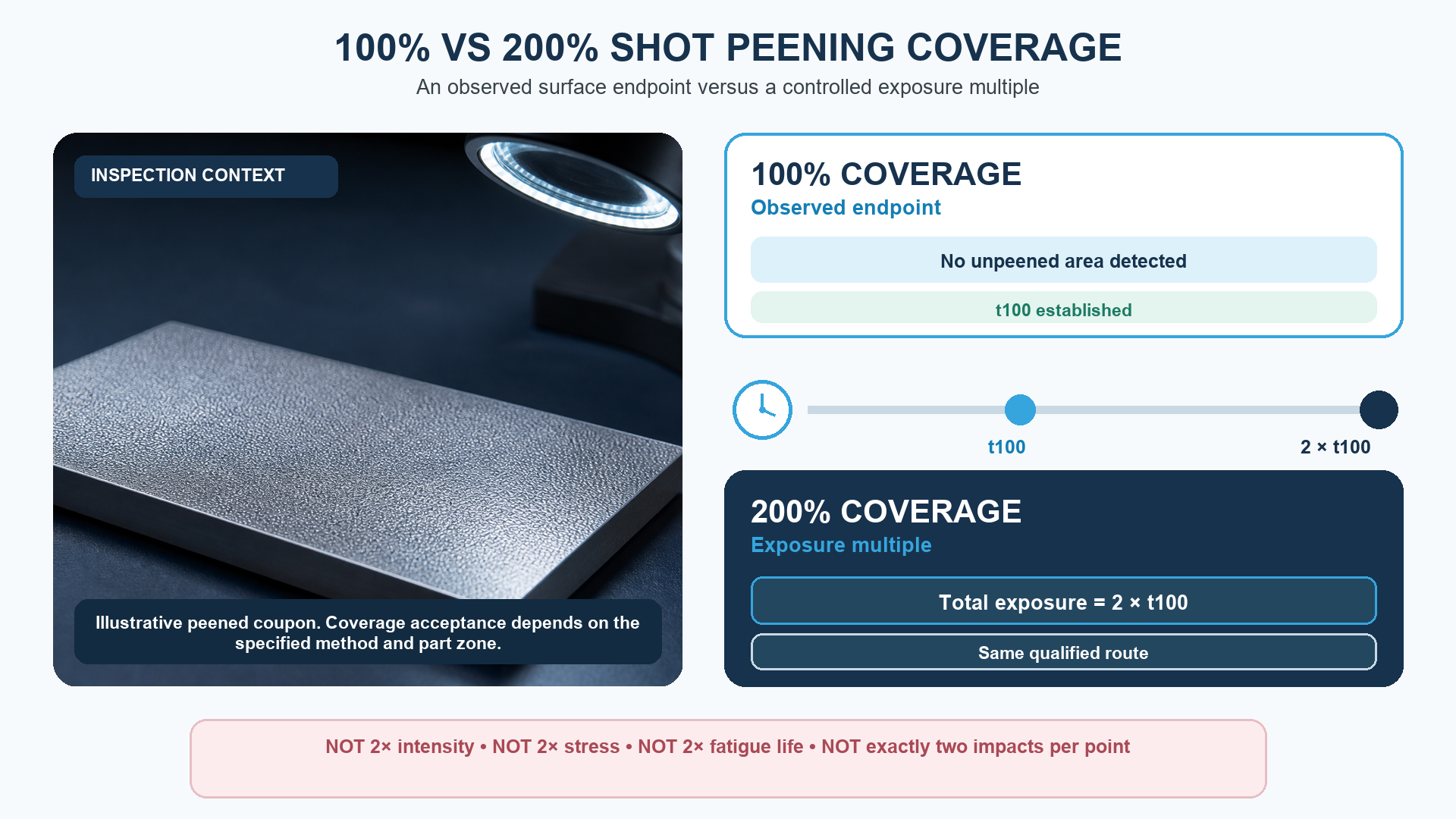
Figure 1. 100% coverage establishes t100; 200% normally controls total exposure at 2 × t100 under the same qualified route.
Figure 1 separates the observable end point from the exposure multiple. At 100%, the approved inspection establishes t100 on the required surface. At 200%, production applies a total exposure of 2 × t100 under the same qualified route. The realistic coupon is illustrative; it is not an acceptance standard or a representation of a specific part result.
What is the difference between 100% and 200% shot peening coverage?
The difference is an exposure multiple, not an area larger than the part. Initial 100% coverage is a surface-inspection result: the specified area shows no detectable unpeened islands under the approved evaluation method and conditions. Once the time to that state has been established as t100, a 200% requirement normally sets total exposure at 2 × t100 under the same controlled process route.
This distinction matters because the word percentage is used in two ways. Up to initial complete coverage, it describes how much of the required surface appears impacted. Above 100%, the complete area cannot become physically larger, so the number becomes shorthand for additional controlled exposure referenced to t100. NASA technical reports use this convention explicitly: one defines 200% as double the time needed to attain 100% coverage, and another defines higher coverage values as multiples of the time needed to indent the full exposed surface.
In this article, t100 is a convenient shorthand for the exposure required to establish initial 100% coverage. It is not presented as a universal symbol defined by every specification. The governing drawing and invoked process specification still take precedence. If a contract defines a different method, cycle basis or verification route, that definition governs the part. A supplier should never convert a coverage note into time, passes or machine settings without confirming the applicable document, revision and approved process development record.
| Requirement | Operational meaning | What it does not prove |
|---|---|---|
| 100% coverage | No unpeened area is detectable on the specified surface using the approved evaluation method and inspection conditions | A specific intensity, residual-stress profile, fatigue-life increase or universal process time |
| 150% coverage | Common notation for total exposure of 1.5 × t100 under the same controlled route, if the governing requirement uses this convention | Exactly 1.5 impacts at every point or 150% of the physical area |
| 200% coverage | Common notation for total exposure of 2 × t100 under the same controlled route | Twice the Almen intensity, twice the compression or twice the fatigue life |
| Coverage above 100% | An exposure-time multiple referenced to an established initial-coverage time | A directly observable area percentage greater than the whole surface |
Table 1. Above initial complete coverage, the percentage is an exposure multiple rather than additional physical area.
CORE FORMULA If t100 = 6 minutes under the qualified route, 200% coverage normally means 12 minutes total exposure, not 6 minutes plus an unrelated second process and not twice the intensity.
What exactly does 100% shot peening coverage mean?
100% coverage means the required surface has reached the specified visual end point: no unpeened area is detectable using the approved evaluation method, lighting, magnification, access and acceptance criteria. It does not mean that every microscopic point received the same number of impacts. Random media impacts overlap, and the observable surface is evaluated for remaining unpeened islands rather than for a perfectly uniform impact count.
The word required is essential. Coverage applies to the treatment zone defined by the drawing or process instruction, not automatically to every visible face of the component. Masked fits, threads, sealing surfaces, sharp edges or other exclusions can be intentionally unpeened. Conversely, a small root or fillet can be the true acceptance zone even when broad adjacent surfaces look completely treated.
The inspection method must be capable of resolving treated and untreated areas. Depending on the governing requirement and part, this can involve direct visual examination, magnification or an authorised fluorescent-tracer technique. Surface finish, colour, contamination, lighting and geometry can affect detectability. The method, operator qualification and acceptance conditions therefore belong in the controlled route rather than in an informal shop-floor judgement.
INSPECTION PRINCIPLE 100% coverage is only as meaningful as the defined surface, observation method and acceptance conditions used to establish it.
How is 200% shot peening coverage calculated?
First establish t100, the exposure required to reach initial complete coverage on the authorised part feature or representative geometry. Then multiply that baseline by the specified coverage factor while keeping the qualified process conditions controlled. For the common notation, 150% corresponds to 1.5 × t100, 200% to 2 × t100 and 300% to 3 × t100. Fractional times must be translated into a reproducible machine programme, number of passes, traverse schedule or other controlled exposure variable.
For example, suppose a gear-root trial reaches initial complete coverage after three identical passes at the approved nozzle angle, distance, media flow and part motion. A 200% requirement would normally call for six total equivalent passes under that same route. It would not authorise a faster wheel, higher pressure, different nozzle position or different media to save time unless those changes were separately approved and their effects on intensity, coverage and the part were established.
The baseline cannot be borrowed casually from another part. t100 depends on geometry, presentation, masking, media condition, flow, nozzle or wheel relationship, motion, fixture, equipment and the inspection method. Even within one component, a broad face may reach complete visual coverage sooner than a shielded root. Process development should use the controlling relevant location, an authorised representative feature or a validated method that accounts for the geometry.
WORKED EXAMPLE t100 = 3 passes; required multiplier = 2.0; production exposure = 6 equivalent passes. Intensity remains a separate controlled result.
Does 200% coverage mean every point is hit twice?
No. Shot impacts are statistical and overlapping, so an exposure multiple cannot guarantee exactly two impacts at every microscopic location. Some points will receive more impacts than others. The 200% notation controls total exposure relative to the established t100 baseline; it is not a map of individual impact counts.
It also does not mean that a second visual layer must be identified. After initial complete coverage, the surface is already fully impacted according to the specified observation method. Continuing to 2 × t100 adds impacts and provides the required exposure multiple, but the inspector cannot normally prove 200% merely by seeing a surface that looks more heavily peened. The production recipe and records are therefore central to acceptance above 100%.
A diagram that colours the surface twice can be useful for explaining time, but it becomes misleading if it suggests every indentation has a paired second indentation. The correct mental model is one controlled random-impact process run for a defined multiple of the established baseline time.
Is shot peening coverage the same as Almen intensity?
No. Intensity and coverage answer different questions and require different evidence. Peening intensity characterises the effect of the media stream using the applicable Almen tools and method. Coverage evaluates whether the specified part surface has been impacted and, above 100%, controls exposure relative to t100. Correct intensity does not prove complete coverage, and complete coverage does not prove correct intensity.
A machine can produce the required intensity while missing a recessed fillet because the stream cannot reach it at the necessary presentation. The opposite problem is also possible: a broad surface may appear fully covered while the media stream operates outside the released intensity range. A qualified route must satisfy both requirements at the specified locations and frequencies.
Residual stress and fatigue performance are further downstream questions. Neither a 200% coverage record nor a conforming Almen record automatically establishes a particular residual-stress profile or life increase in the component. Those claims require the component-specific evidence and acceptance method authorised by design or contract.
| Engineering question | Controlled characteristic | Typical evidence |
|---|---|---|
| How severe is the peening stream? | Peening intensity | Almen strip, holder, gage and saturation-curve or verification procedure required by the invoked document |
| Has the specified part surface been impacted? | Initial coverage | Approved direct, optical or tracer-assisted surface evaluation on the defined area |
| How long is the part exposed after t100 is known? | Coverage multiple / exposure | Qualified cycle time, passes, traverse or equivalent controlled programme |
| What near-surface stress state was produced? | Residual-stress profile | A specified measurement method such as X-ray diffraction when contractually required |
| What durability change is achieved? | Component performance | Approved test, analysis, precedent or service evidence representative of the actual part |
Table 2. Intensity, coverage, residual stress and component performance are separate engineering questions.
DO NOT SUBSTITUTE Intensity controls the peening stream. Coverage controls treatment of the specified surface and its exposure. One result cannot be used as evidence for the other.
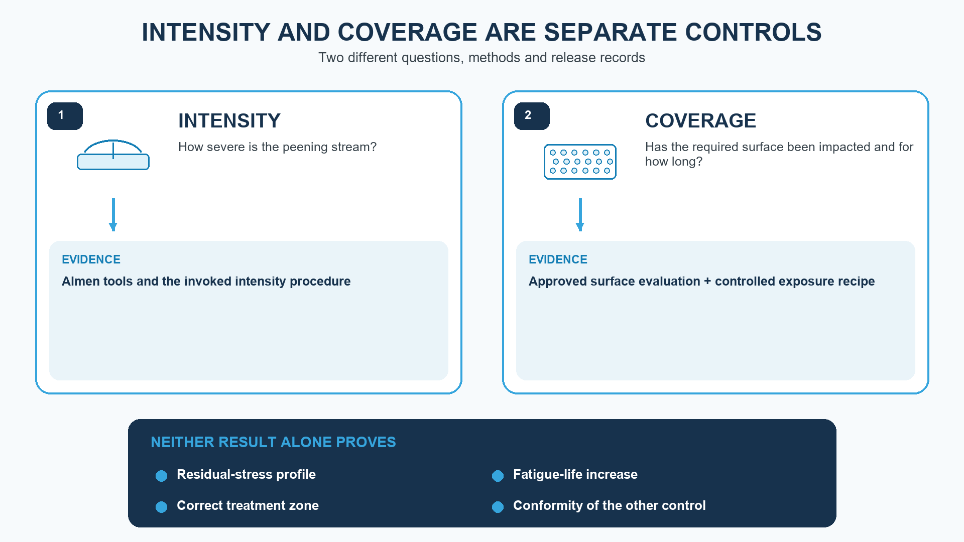
Figure 2. Intensity and coverage answer different questions and require separate evidence.
Figure 2 prevents a common substitution error. Almen evidence characterises the peening intensity, while surface evaluation and the locked exposure recipe support coverage. Neither result alone proves the residual-stress profile, fatigue-life increase, correct treatment zone or conformity of the other control.
Why do specifications require 200% coverage?
A specification may require 200% coverage to provide a defined exposure beyond the first observed complete-coverage point. The additional exposure can reduce sensitivity to the exact moment at which the last visible unpeened island disappears and can support repeatability across a controlled process. It is an engineering requirement, not a universal rule that more exposure is always better.
Complex geometry is one reason an approved process may use a multiplier. Roots, fillets, splines, intersections and partially shielded surfaces can receive impacts at different rates. Once t100 has been established on the controlling zone, a specified multiple creates a reproducible production cycle. The multiplier does not excuse poor access: if a zone cannot be reached, doubling exposure to accessible surfaces does not solve the underlying geometry problem.
The required value may also reflect prior fatigue testing, programme precedent, customer rules or a validated manufacturing route. That basis is component- and contract-specific. SP Center can help translate an approved requirement into tooling, presentation, masking and records, but the processor should not increase a design-controlled coverage value without the agreed engineering approval route.
Can coverage be too low or exposure too high?
Coverage below the specified requirement can leave untreated islands in a surface where cyclic tensile stress is important. That is not corrected by a good Almen result elsewhere. Access, presentation, media trajectory, masking and motion must be corrected so the actual acceptance zone receives the required treatment.
Extra exposure is not automatically harmless. SAE J2277 states in its public scope that inadequate or excessive coverage can be detrimental to fatigue strength and component life. Depending on material, hardness, geometry and process severity, unnecessary exposure can contribute to greater roughness, cold work, local folding or lapping, edge damage, dimensional change or distortion. NASA investigations likewise discuss trade-offs among coverage, cold work, lapping and cracking behaviour in specific superalloy applications.
The practical control is a validated window, not a slogan such as more is better. Use the specified exposure multiple, hold the qualified media and machine route, monitor the required inputs and screen changes. If production capability needs a wider window, establish it through authorised process development and component evidence rather than by silently extending cycle time.
| Condition | Why it matters | Engineering response |
|---|---|---|
| Below required coverage | Unimpacted islands can remain in a fatigue-critical zone | Correct access or presentation and re-establish the route; do not infer coverage from intensity |
| Nominal t100 not representative | A flat or accessible area can hide a shadowed root, fillet or recess | Determine coverage at the hardest relevant geometry or an authorised representative feature |
| Uncontrolled extra exposure | Additional impacts can increase roughness, cold work, edge damage or distortion | Use only the specified multiplier and validated process window |
| Process conditions changed | The original t100 may no longer describe the altered media stream or presentation | Assess the change and repeat the required intensity or coverage demonstrations |
| Inspection cannot distinguish treated surface | The coverage decision becomes subjective or non-repeatable | Improve preparation, lighting, magnification, tracer method, training or acceptance criteria |
Table 3. Coverage risk can come from access, an unrepresentative baseline, excessive exposure, process changes or inspection limitations.
ENGINEERING LIMIT 200% is a defined requirement, not permission for unlimited peening. Both insufficient and excessive exposure can be unacceptable.
How do geometry and inspection method affect t100?
t100 is specific to what is exposed and how it is inspected. A flat witness panel is easier to view and may receive a more direct media stream than a gear root, internal corner, deep recess or intersecting feature. If the trial location is not representative of the production acceptance zone, the resulting exposure multiple can be technically neat but geometrically wrong.
Process development should identify the slowest relevant area to reach complete coverage, or use an authorised representative specimen that faithfully reproduces access and presentation. Nozzle angle, stand-off, wheel position, part rotation, traverse, fixture shielding, masking boundaries and media rebound can change local impact density. Coverage mapping can be useful during development even when serial release uses a locked recipe.
Inspection repeatability also matters. A rough or previously treated surface can make unpeened islands difficult to distinguish. A fluorescent tracer may improve visibility in an approved route, but the method must be qualified for the surface and geometry, correlated with the governing acceptance method, and applied, cured, exposed and inspected under a controlled procedure. Magnification and lighting should be controlled when they affect the pass/fail decision. Photographs can support records, but they do not replace the specified method or acceptance authority.
How should 100% and 200% coverage be developed and verified?
Development begins with an unambiguous engineering requirement. The drawing and flow-down should identify the treatment zone, exclusions, intensity, coverage, media restrictions, sequence, inspection method and records. The processor then establishes the peening intensity and the initial coverage baseline using the applicable equipment, fixture, programme and part presentation.
Once t100 is established, the specified multiplier is converted into a locked production cycle. Serial verification then focuses on execution: correct equipment and programme, media control, intensity verification at the required frequency, fixture and masking condition, complete cycle, traceability and nonconformance status. A visual check can still be required, but it cannot by itself prove a 200% time multiple after the surface is already fully covered.
Change control closes the loop. A different part revision, hardness, incoming finish, media lot or size, pressure, wheel speed, nozzle, fixture, motion, programme, machine, inspection route or downstream operation can affect the established basis. The applicable quality plan should define whether the change requires review, repeat coverage demonstration, renewed intensity work, first-article activity or customer approval.
| Stage | Required action | Release evidence |
|---|---|---|
| 1. Define | Identify the treatment zone, exclusions, governing document, intensity range and coverage requirement | Controlled drawing, specification and purchase-order flow-down |
| 2. Establish intensity | Develop or verify the peening intensity independently of part coverage | Required Almen record and accepted process window |
| 3. Establish t100 | Use representative geometry and the approved inspection method to find initial complete coverage | Documented coverage demonstration and inspection conditions |
| 4. Apply multiplier | Set total production exposure to the specified multiple of t100 while holding the qualified route | Locked recipe, passes, time or equivalent programme value |
| 5. Verify execution | Control media, equipment, presentation, masking, intensity and cycle completion | Batch or part records, traceability and nonconformance status |
| 6. Control changes | Review changes to part, media, equipment, nozzle or wheel, fixture, programme, sequence or inspection | Approved equivalence, re-demonstration or requalification decision |
Table 4. A controlled route links the coverage requirement to t100, production exposure and release records.
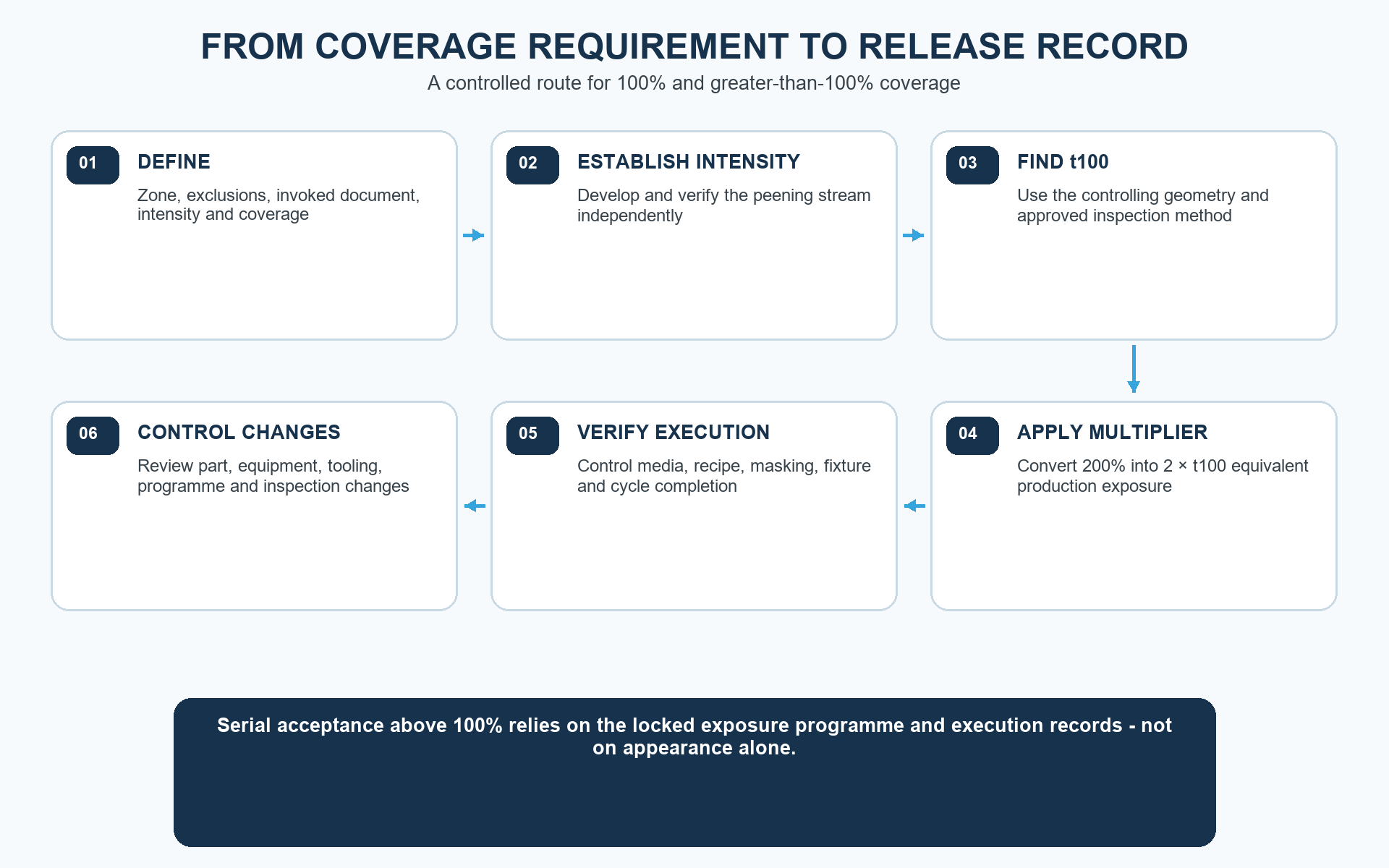
Figure 3. Coverage development connects the engineering requirement, initial t100 demonstration, production exposure and release evidence.
Figure 3 shows why 200% cannot be released from appearance alone. The route first defines the requirement and establishes intensity, then finds t100 on representative geometry, applies the approved multiplier, verifies execution and controls changes that could invalidate the baseline.
How should a drawing or purchase order specify coverage?
A useful coverage note names the governing document and revision, defines the required percentage or exposure multiple, and points to the exact treatment zone. It should also state any masking, exclusions, transition rules, intensity requirement, media restriction, sequence and release records needed by the contract. The drawing, purchase order and process specification must agree on identifiers and precedence.
Avoid phrases such as full coverage, double peen or visually complete when they are not tied to a controlled definition. Full coverage can be read as initial 100%, while double peen might mean two passes, two machines, two media sizes or 200% exposure. Clear language connects the design requirement to a measurable development method and a reproducible production route.
A supplier quotation also needs enough information to assess feasibility. Provide controlled drawings, material and heat treatment, incoming surface condition, quantities, treatment and exclusion zones, governing standards, complete intensity and coverage requirements, prior and downstream operations, qualification scope and required records. Missing information should be resolved before production parameters are finalised.
| Specification element | Clear requirement | Ambiguity to avoid |
|---|---|---|
| Treatment area | Identify peened surfaces, boundaries, transitions and excluded or masked features | Shot peen complete |
| Intensity | State the complete range, strip type and governing method | Use medium intensity |
| Coverage | State 100%, 150%, 200% or the required multiple and define the invoked method | Full coverage |
| Inspection | State the method, magnification or tracer route, lighting, representative zone and acceptance authority | Visually inspect |
| Exposure control | Connect the production recipe to the established t100 and required multiplier | Run long enough |
| Records | List intensity, coverage demonstration, media, recipe, traceability and release records | Certificate required |
| Change control | Define which changes require approval, re-demonstration or requalification | Equivalent process allowed |
Table 5. Clear specification language removes ambiguity before process development and quotation.
RFQ SUPPORT Send the controlled drawing, material condition, treatment zones, invoked documents, intensity, coverage, quantities and record requirements to [email protected] or call +48 519 772 773.
What are the most common mistakes with 200% coverage?
The first mistake is treating 200% as a visible area measurement. Once 100% of the required surface is impacted, there is no additional physical area to count. The second mistake is doubling machine pressure, wheel speed or intensity instead of doubling the established exposure. That changes process severity and may move the route outside the qualified window.
Another mistake is timing from an unrepresentative easy surface. If a broad face reaches 100% before the root or fillet, 2 × the easy-surface time may still leave the critical feature below requirement. Conversely, choosing an arbitrary long cycle without establishing t100 can create unnecessary exposure and still fail to document the required basis.
The final mistake is assuming that 200% coverage proves a fatigue result. Coverage is one controlled input among intensity, media, material, surface condition, geometry, sequence and validation. Publication, quotation and certificate language should state what was controlled without turning process conformity into an unsupported performance guarantee.
- Do not interpret 200% as twice the physical area or exactly two impacts per point.
- Do not double pressure, wheel speed or intensity to satisfy a time-based coverage multiple.
- Do not establish t100 on a location that does not represent the controlling treatment zone.
- Do not use appearance alone to certify an exposure value above initial complete coverage.
- Do not assume that extra exposure is harmless or that it produces a proportional fatigue benefit.
- Do not replace the invoked revision with a newer publisher revision without authorised approval.
What are the common myths about 100% and 200% coverage?
200% coverage means the entire surface is peened twice. This is incorrect. It normally means twice the established t100 exposure under the same controlled route; individual points receive a statistical, non-uniform number of overlapping impacts.
200% coverage is twice the Almen intensity. This is incorrect. Intensity and coverage are independent controls with different methods and evidence.
The inspector can see whether a surface is at 200%. Not by area alone. Initial complete coverage can be observed; the greater-than-100% multiple is demonstrated mainly through the qualified exposure programme and records.
More coverage is always better. This is incorrect. The specified, validated exposure is required. Excessive coverage can be detrimental in some applications.
Correct intensity guarantees complete coverage. This is incorrect. A conforming stream can still miss a shielded root, fillet or recess.
200% coverage proves twice the fatigue life. This is incorrect. Component performance requires authorised evidence for the actual material, geometry, load, surface and process route.
Frequently asked questions about shot peening coverage
What is 100% coverage in shot peening?
100% coverage is the condition at which no unpeened areas are detectable on the specified treatment surface using the approved inspection method and conditions. It is a coverage result, not an intensity or fatigue-life result.
What is 200% coverage in shot peening?
200% coverage normally means total exposure equal to 2 × the established time required to reach initial 100% coverage under the same controlled process route. The governing drawing and specification define the actual requirement.
If 100% coverage takes 10 minutes, how long is 200%?
Under the common exposure-multiple convention, 200% would be 20 minutes total at the same qualified conditions. Confirm that the invoked requirement uses this definition and that time is the controlled equivalent for the actual machine programme.
Does 200% coverage mean two shot impacts at every point?
No. Media impacts are random and overlapping. The notation controls exposure relative to t100; it does not guarantee an exact impact count at each microscopic point.
Can 200% coverage be checked visually?
Initial 100% can be evaluated visually or with another approved surface method. Once the surface is fully covered, a visual area check alone cannot normally prove a 2 × exposure; the qualified programme and execution records are needed.
Is 200% coverage the same as double peening?
Not necessarily. The phrase double peening can describe a separate two-stage process, different media or two operations. Use the exact coverage and process wording from the invoked engineering document rather than treating the terms as synonyms.
Does 200% coverage increase Almen intensity?
Not by definition. Intensity is derived and verified separately. Longer part exposure can add impacts, but it does not convert the specified coverage percentage into a different Almen intensity requirement.
Can shot peening coverage be excessive?
Yes. SAE J2277 notes that inadequate or excessive coverage can be detrimental to fatigue strength and component life. Use the specified exposure multiple and validated window rather than extending time without approval.
Where should t100 be established on a complex part?
Use the controlling relevant treatment zone or an authorised representative feature that reproduces access and presentation. An easy flat surface may not represent a root, fillet, recess or shadowed area.
What should I send SP Center for a coverage review?
Send the controlled drawing and revision, material and heat treatment, treatment and exclusion zones, governing specifications, intensity and coverage requirements, quantities, manufacturing sequence, qualification scope and required records. Call +48 519 772 773 for an initial review.
Key takeaways
- 100% coverage is an observable end point on the specified surface under a defined evaluation method.
- 200% coverage normally means total exposure of 2 × t100 under the same qualified route.
- A greater-than-100% value is an exposure multiple, not a physical area greater than the component surface.
- Coverage does not define intensity, residual stress, exact impact count or component fatigue life.
- t100 must represent the controlling geometry, access, presentation and inspection conditions.
- The qualified programme and records demonstrate exposure above initial complete coverage.
- Both insufficient and excessive coverage can be unacceptable; the invoked requirement and revision govern.
Related SP Center shot peening guides
- What Is Shot Peening – How It Works and When to Use It – the process mechanism and first application screen
- Shot Peening Process Step by Step – how approved requirements become a controlled production route
- 12 Common Mistakes in Shot Peening Specifications – how to remove ambiguity from drawings and purchase orders
- Designing for Shot Peening – treatment zones, access, masking, sequence and design authority
Technical references
1. SAE J2277_202301: Shot Peening Coverage Determination, revised January 2023
2. SAE J443_202512: Procedures for Determining and Verifying Peening Intensity, revised December 2025
3. SAE J442_202602: Tools for Peening Intensity Determination and Verification, revised February 2026
4. SAE AMS2430U: Shot Peening, revised April 2018
6. NASA/TM-20230007568: Recrystallization of a Shot Peened Single Crystal Nickel-Base Superalloy
REFERENCE CONTROL The contractually invoked document and revision govern the part. Current publisher status does not replace an invoked revision or customer flow-down without authorised approval.
Shot peening coverage support from SP Center
SP Center supports treatment-zone and masking review, coverage demonstrations, t100 and exposure-multiplier development, tooling and programme concepts, Almen intensity and media control, qualification planning, controlled serial shot peening, traceability and reporting against confirmed engineering requirements.
SP Center – We strengthen what matters.
Shot peening service: spcenter.pl/en/services/shot-peening/
SP Center sp. z o.o. | ul. Biznesowa 5, 35-213 Rzeszow, Poland | [email protected] | +48 519 772 773
Author: Paweł Kmieć