


A practical ten-stage engineering workflow for requirements, feasibility, intensity, coverage, qualification, production and traceability
A controlled shot peening process begins with the released requirement and ends with traceable evidence—not with a machine setting. The route must connect drawing and material condition, feasibility, equipment and media, Almen-intensity verification, coverage acceptance, component validation when invoked, qualification, serial execution, final review and authorized reporting. Each stage answers a different question and creates a controlled output.
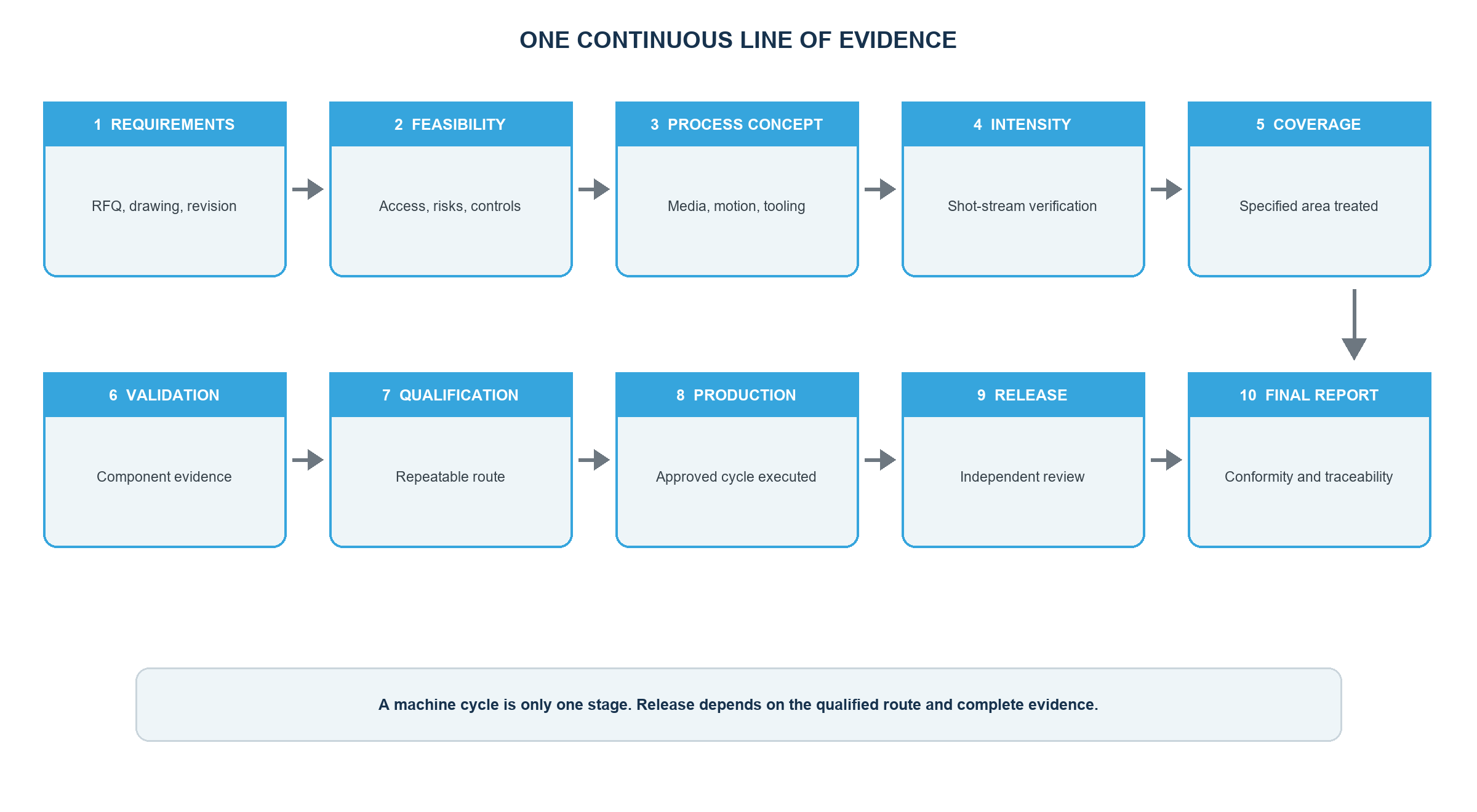
Why is shot peening controlled as a complete process?
The intended surface state cannot normally be confirmed through one final inspection. Consistency depends on controlling the requirement, stream, media, geometry, motion, masking, exposure, equipment, personnel, inspection, records and changes as one system.
Automation or computer monitoring can strengthen observation and traceability of defined inputs. It does not replace design authority, Almen verification, coverage assessment, surface acceptance or part-level validation where required.
Step 1: Review the controlled requirement
Confirm part number, drawing, revision, contractual hierarchy, material and heat-treatment condition, treatment and exclusion zones, complete intensity and coverage requirements, media restrictions, process sequence, records, tests, packaging and approval authority. Record missing or conflicting information and stop only the affected decision until it is formally clarified.
Step 2: Confirm feasibility
Review access, impact angle, shadowing, bores, roots, edges, thin sections, masking, tooling, part motion, loading, media removal, distortion and inspection access. A technically desirable zone is not feasible until it can be reached, controlled and accepted on the proposed equipment.
Step 3: Develop the process concept
Select a proposed equipment type, media family, nozzle or wheel arrangement, fixture, masking, part motion, monitoring and inspection route within the authorized requirements. Do not substitute pressure, wheel speed or exposure time for a design-controlled Almen intensity. Document assumptions and planned trials.
Step 4: Establish and verify Almen intensity
Use the applicable Almen strip, holder, gage, location and procedure. Develop a saturation curve or perform the required intensity verification as invoked. Record the accepted intensity and configuration. The result verifies the qualified stream; it does not directly measure residual stress in the component or prove coverage.
Step 5: Demonstrate coverage
Define the component area, inspection method, lighting, magnification, surface condition, boundaries and acceptance rule. Establish a qualified exposure route on representative geometry. If 150% or 200% coverage is invoked, apply the specified exposure multiplier relative to the qualified time to complete coverage under unchanged conditions.
Additional exposure cannot correct a shadowed or inaccessible area and may overwork an open surface. Fluorescent, tracer or digital methods require approval, qualification and correlation where used.
Step 6: Perform component validation when required
Residual-stress measurement, fatigue testing, distortion, roughness, SCC or other functional testing applies only when required by the customer, drawing or qualification plan. Define representative parts or specimens, preparation, location, method, limits and decision authority. Component validation must remain separate from stream verification and routine surface acceptance.
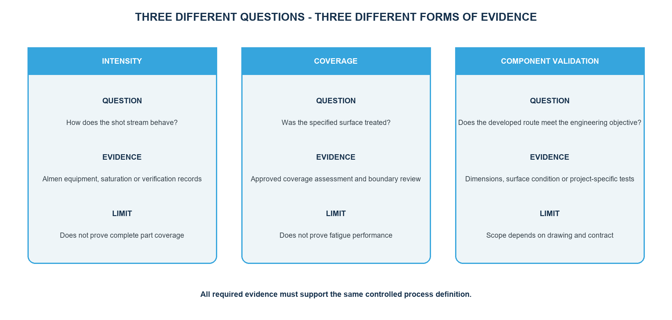
| Evidence layer | Typical content | What it does not prove by itself |
|---|---|---|
| Process verification | Almen result, media condition, equipment configuration, program, motion and monitored inputs | Complete component coverage or part performance |
| Component surface acceptance | Coverage, boundaries, surface condition, damage, contamination and invoked dimensions or roughness | Qualified stream intensity or fatigue-life improvement |
| Component validation | Residual-stress profile, fatigue, SCC, distortion or functional testing when required | Routine execution of every production batch unless separately recorded |
Table 1. Process verification, component surface acceptance and validation answer separate questions.
Step 7: Qualify the production route
Combine the approved equipment, media, working mix, tooling, masking, motion, intensity, coverage route, monitored inputs, inspections, records and reaction plans into controlled instructions. The qualification basis must identify the part or family, material condition, configuration, evidence, limits and change authority.
Step 8: Execute serial production
Before processing, verify order and part identity, revision, incoming condition, equipment and program status, tooling, media, inspection readiness and required checks. During processing, protect recipe control and traceability. Record interruptions, alarms, out-of-limit conditions and operator actions.
Do not improvise extra passes, media changes, re-peening or rework. Follow the approved reaction and nonconformance process.
Step 9: Complete final review and release
Confirm coverage and all invoked surface, dimensional or cleanliness criteria on the actual component. Review process-verification records, traceability, nonconformance status, approved dispositions, required customer forms and completion of any component validation. Release authority must be defined and independent where required.
Step 10: Issue the final report
The final certificate or report should identify the part, drawing revision, order, batch, quantity, governing specification and route, and the evidence required by the contract. It should link intensity and coverage results, media and equipment traceability, inspections, deviations and authorized release without claiming tests or approvals that were not performed.
Which decisions and records belong to each stage?
| Stage | Primary decision | Representative controlled output |
|---|---|---|
| 1. Requirement review | Is the contractual and technical baseline complete and consistent? | Review record, open-item register and document hierarchy |
| 2. Feasibility | Can every required zone be treated, protected and inspected? | Access, masking, tooling, handling and risk review |
| 3. Process concept | Which equipment, media, tooling, motion and controls can meet the requirement? | Proposed route and development plan |
| 4. Intensity | How is the required stream intensity established and verified? | Almen setup, saturation or verification evidence and accepted range |
| 5. Coverage | How is complete treatment of the specified component area demonstrated? | Qualified exposure route, method, boundaries and acceptance evidence |
| 6. Component validation | Is part-level performance evidence invoked? | Defined specimens or parts, tests, limits and approval |
| 7. Qualification | Does the combined route meet the released requirement? | Approved trials, instructions, records and change baseline |
| 8. Serial production | Was the approved route executed without unresolved interruption or change? | Batch traveller, parameter, media, verification and inspection records |
| 9. Final review | Are part acceptance and all required records complete? | Conformity review, nonconformance status and release decision |
| 10. Final report | Can the delivered batch be reconstructed and its conformity understood? | Certificate or report linked to part, batch, route and evidence |
Table 2. Ten stages create a traceable chain from requirement readiness to final report.
What commonly causes a route to fail?
- Starting from machine settings before the drawing and material condition are understood.
- Unclear treatment boundaries, inaccessible geometry or unqualified masking.
- Using intensity as proof of coverage or coverage as proof of residual stress.
- Uncontrolled media condition, equipment change, program revision or fixture replacement.
- Missing reaction plan for alarms, interruption, out-of-limit data or retained media.
- Production release before customer-owned decisions or qualification evidence are complete.
- A final report that cannot reconstruct the actual part, batch, route and disposition status.
What should be sent to SP Center for a process review?
Send the current drawing and revision, material and heat-treatment condition, marked treatment and exclusion zones, governing documents, intensity and coverage requirements or proposal authority, part dimensions and mass, quantities and batch pattern, required validation, records, packaging and target date to [email protected].
Frequently asked questions
How many stages are in a controlled shot peening process?
This guide uses ten practical stages from requirement review to final report. A company may group them differently, but every technical decision, approval and evidence layer must remain controlled.
Does shot peening begin with machine settings?
No. It begins with the current drawing, material condition, treatment zones, governing documents, design objective, evidence and approval authority. Settings are developed only after feasibility and requirement review.
What is the difference between intensity and coverage?
Almen intensity verifies the qualified stream under the applicable Almen arrangement. Coverage accepts the specified component surface. A conforming result for one does not prove the other.
Is a saturation curve required for every production batch?
Not automatically. The governing specification and approved process plan determine whether a full curve, intensity verification or another defined check is required for qualification and production.
Is residual-stress measurement required for every job?
No. XRD or another residual-stress method is used when invoked for qualification, validation, investigation or acceptance. It does not routinely replace Almen verification, coverage or process records.
What does process qualification prove?
It shows that a defined configuration and controlled route met the released requirements and specified evidence on the qualified basis. It does not authorize unreviewed changes or guarantee universal component life.
What happens if the cycle is interrupted?
Stop and follow the approved reaction plan. Record the condition, protect traceability, assess exposure and part status, obtain any required disposition, and resume or restart only under authorized instructions.
What should the final report include?
Include the part and drawing revision, order and batch, quantity, process route or specification, required intensity and coverage evidence, media and equipment traceability, inspections, nonconformance status and authorized release.
Key takeaways
- Begin with controlled requirements, not machine settings.
- Qualify access, tooling, media, motion and inspection as one route.
- Keep Almen intensity, coverage, surface acceptance and component validation distinct.
- Control serial execution, interruption, nonconformance and change.
- Release only after the actual batch and required evidence are complete.
- Make the final report traceable without adding unsupported claims.
Related SP Center guides
Technical references
1. SAE AMS2430U: Shot Peening, revised April 2018
2. SAE AMS2432E: Shot Peening, Computer Monitored, revised October 2022
3. SAE ARP7488: Peening Design and Process Control Guidelines, issued January 2018
4. SAE J442_202602: Tools for Peening Intensity Determination and Verification, revised February 2026
5. SAE J443_202512: Procedures for Determining and Verifying Peening Intensity, revised December 2025
6. SAE J2277_202301: Shot Peening Coverage Determination, revised January 2023
Standards note: The complete revisions invoked by the contract and customer requirements govern.
Author: Paweł Kmieć
Discuss a process route: +48 519 772 773 | [email protected]