


Understand particle velocity as a stream characteristic generated by media, equipment and geometry—not as a substitute for Almen intensity or component acceptance
Particle velocity strongly influences the severity of an individual shot impact, but a production stream contains particles with different masses, speeds and directions. Air pressure and wheel speed are machine inputs; particle velocity is a resulting stream characteristic; Almen intensity is a standardised measured response; component coverage and surface acceptance are separate outputs. A qualified process keeps these evidence layers distinct.
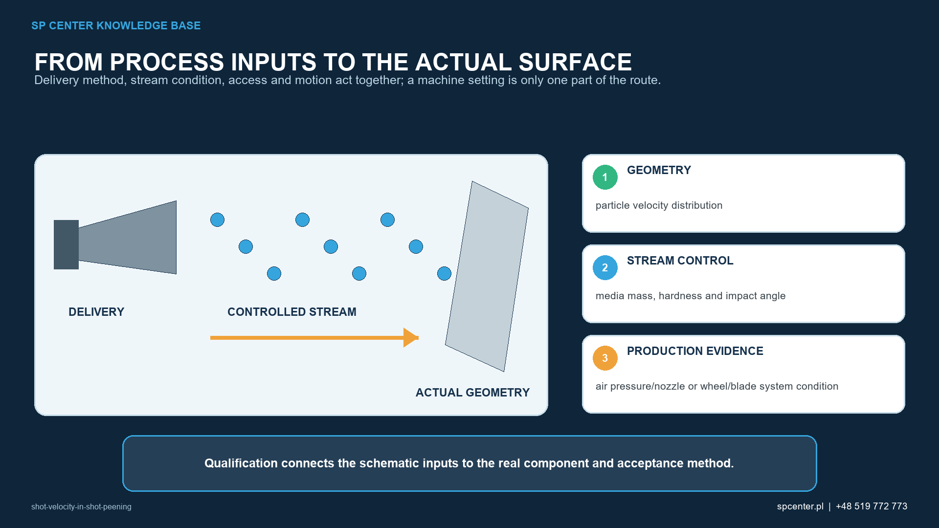
How does particle velocity affect impact energy?
For one particle, kinetic energy is expressed as Ek = ½mv2. The square term explains why a velocity change can materially affect impact severity, while particle mass depends on size and density. The equation is a physical explanation—not a model of the complete process. Contact mechanics, media hardness and shape, impact angle, particle flux, rebound, component material and surface condition also affect the result.
| Quantity | Engineering meaning | Do not treat it as |
|---|---|---|
| Air pressure or wheel speed | Equipment input that influences particle acceleration | A direct measurement of particle velocity or Almen intensity |
| Particle velocity | A distribution of particle speeds and directions in the real stream | One identical value for every particle or a complete process result |
| Kinetic energy | For one particle, Eₖ = ½mv²; mass and velocity act together | A prediction of coverage, roughness, residual stress or fatigue life |
| Almen intensity | Standardised response determined and verified with the invoked Almen procedure | A direct measurement of component velocity, residual stress or surface acceptance |
| Component coverage | Extent of impact evidence over the required surface under the approved method | Proof of correct intensity or subsurface stress state |
Table 1. Equipment inputs, stream characteristics, standardised verification and component acceptance are not interchangeable.
Why is higher velocity not automatically better?
The objective is a stable process window that achieves the required Almen intensity and component coverage while maintaining permitted roughness, surface integrity, dimensions and distortion. Raising a setting beyond that demonstrated window is a process change, not a free performance margin.
Equal Almen intensity achieved with different media size, density, hardness or velocity combinations does not automatically produce equal roughness, cold work, residual-stress profile or fatigue behaviour. Where those outcomes are design requirements, use the specified component inspection or validation rather than calculating them from nominal velocity.
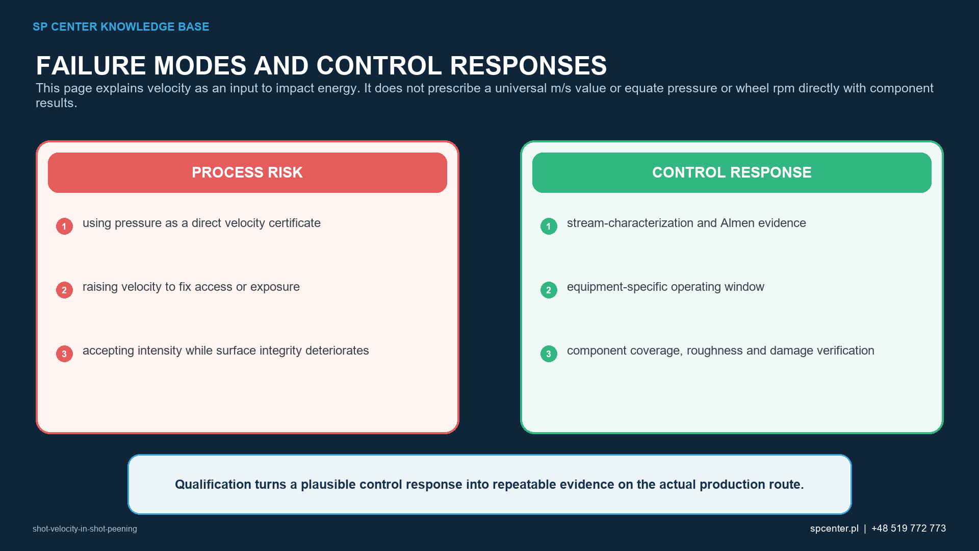
How is velocity generated in pneumatic and wheel systems?
| Acceleration system | Variables affecting the stream | Control principle |
|---|---|---|
| Pneumatic air-blast | Pressure at a defined location, available air flow, mixing, hose loss, nozzle/lance geometry and wear, media loading | Lock and monitor the qualified configuration; do not convert pressure to velocity with a universal factor |
| Centrifugal wheel | Wheel diameter and speed, blade and control-cage condition/position, feed rate, media population and wear | Control the complete wheel assembly and hot-spot delivery, not rpm alone |
| Nozzle or wheel to component | Stand-off, orientation, impact angle, footprint, masking, part motion and shadowing | Verify the real component geometry and worst-access prescribed location |
| Media circuit | Material, size distribution, density, hardness, shape, breakdown, classification and mass flow | Treat any significant media or separator change as a possible change to the velocity–intensity relationship |
Table 2. Velocity comes from an equipment-specific acceleration system and remains linked to component delivery geometry.
In a pneumatic system, two machines displaying the same pressure can create different streams. Pressure may be measured at different locations, available air delivery can fall under load, and hose, mixing, nozzle wear or media loading can change acceleration. In a wheel system, rpm alone omits wheel diameter, blade condition, control-cage position, feed and hot-spot alignment.
How do media size, density and mass flow interact with velocity?
Particles at the same speed do not carry the same kinetic energy when their mass differs. Equal-diameter steel, ceramic and glass media have different densities and contact behaviour. Size distribution also changes the particle count associated with a mass flow. Media material, size, hardness, shape and operating condition must therefore be developed together with the velocity-producing configuration.
Media mass flow is not particle velocity, but it changes particle population and can influence acceleration conditions. A stable feeder command is not sufficient when actual flow, separator performance, media breakdown or recovery condition can drift.
Which changes can invalidate the established relationship?
| Changed condition | Possible consequence | Required evidence |
|---|---|---|
| Higher velocity-producing setting | Higher impact severity, roughness, indentation, distortion or media breakdown may occur | Re-establish the authorised process window and component acceptance; do not assume improvement |
| Lower setting | Intensity and local plastic response may fall | Input record, current Almen verification and component evidence required by the route |
| Different media size or density | Particle mass and number population change at the same nominal velocity | Media conformity plus renewed stream/intensity and component assessment |
| Different nozzle, wheel blade or hose | Acceleration, trajectory and footprint can change | Tool/configuration identity and risk-based verification or requalification |
| Changed impact angle or stand-off | Normal velocity component, particle flux and reachable surface change | Qualified geometry, coverage at critical locations and applicable surface evidence |
| Unstable media mass flow | Velocity distribution and particle flux may vary even at a stable displayed setting | Validated monitoring, limits and reaction plan appropriate to the equipment |
Table 3. The direction of a setting change does not establish acceptability; the qualified basis and evidence determine the response.
Why are impact angle, coverage and exposure separate?
Impact angle changes the normal component of particle velocity and local contact response. Stand-off, footprint, shadowing, path overlap and part motion determine whether the stream reaches the required surface. Increasing velocity cannot repair an inaccessible recess, an untreated boundary or an incorrect restart point.
Coverage assesses impact evidence over the specified component surface under the approved method. Almen intensity verifies the standardised stream response. Neither result alone proves the other, and neither is a direct measurement of the component residual-stress profile.
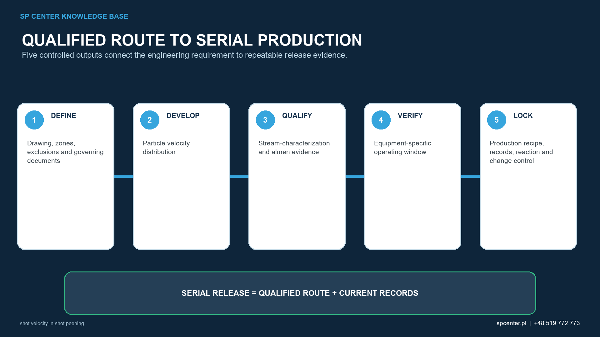
How is a velocity-producing process qualified and controlled?
| Qualification stage | Output | Acceptance boundary |
|---|---|---|
| Define requirements | Governing media, intensity, coverage, treatment zones, surface and dimensional limits | Drawing, specification and customer flow-down remain authoritative |
| Fix configuration | Machine, nozzle/lance or wheel, hoses, feed system, tooling, measurement locations and recipe | A trial does not transfer automatically to changed equipment |
| Establish media population | Approved material, size, hardness, shape, condition and operating-mixture controls | Nominal velocity is meaningless without the media state |
| Develop and verify the stream | Stable inputs, saturation curve and Almen intensity under the invoked procedure | Intensity is not direct component velocity or residual stress |
| Qualify component delivery | Coverage at difficult geometry, boundaries, surface integrity, dimensions and other required evidence | Higher velocity cannot correct shadowing or inaccessible surfaces |
| Control production and change | Limits, monitoring, maintenance, alarms, records, reaction and requalification logic | Completion without alarms proves only monitored execution |
Table 4. Qualification connects machine settings to standardised stream verification and component-level evidence.
Equipment condition protects repeatability. Inspect nozzle or lance identity, wear and restriction; hose routing and leakage; wheel blades and control cage; feed and separator operation; sensors and measurement locations. The control plan should define parameter limits, alarm response, maintenance triggers and the verification or requalification required after relevant changes.
When is direct velocity measurement useful?
Optical or other particle-velocity measurement can support development, troubleshooting or a specifically invoked control plan. The method must be suitable for the media, stream density, measurement volume and equipment geometry, with controlled calibration or validation and data interpretation. A mean value can hide distribution changes. Direct velocity data therefore complements rather than automatically replaces Almen intensity, coverage and component acceptance.
What is shot velocity in shot peening?
It is the speed of individual media particles in the peening stream. A real stream has a distribution of speeds and directions rather than one identical velocity for every particle.
What is the correct shot velocity?
There is no universal value. The authorised equipment settings depend on media, machine configuration, geometry, impact angle, required Almen intensity, coverage and component surface or dimensional limits.
Does air pressure equal shot velocity?
No. Pressure is one input. Available air flow, pressure measurement location, hose losses, mixing, nozzle geometry and wear, media mass flow, particle size and density all influence the resulting stream.
Does wheel rpm directly define particle velocity?
No. Wheel diameter, blades, control cage, feed, media properties and wear also affect launch conditions, stream footprint and delivery to the component.
Does higher velocity always improve shot peening?
No. It may increase impact severity but can also change roughness, indentation, distortion, media breakdown and surface integrity. The objective is a qualified process window, not maximum speed.
Does correct Almen intensity prove the component received the right velocity?
No. Almen intensity is a standardised response of the defined verification setup. It does not directly measure component particle velocity, coverage, residual-stress profile or surface condition.
Can velocity compensate for poor access or incomplete coverage?
No. A particle cannot treat a surface it does not reach. Nozzle or wheel orientation, stand-off, masking, shadowing, path, overlap, rotation and exposure must be qualified for the component.
Must particle velocity be measured directly?
Only when the governing requirement or qualified control plan calls for it. Any direct method must be suitable, calibrated or validated as required, and correlated to the controlled configuration; it does not replace invoked Almen and component checks.
Key takeaways
- Keep machine inputs, particle velocity, Almen intensity and component coverage distinct.
- Use Ek = ½mv2 as a physical explanation, not a complete process model.
- Develop velocity together with media mass, size, density, hardness, shape and flow.
- Control the full pneumatic or wheel acceleration system—not pressure or rpm alone.
- Verify impact angle, access, coverage and surface condition on relevant component geometry.
- Treat significant media, hardware, path or setting changes through authorised change control.
- Use direct velocity measurement only through a defined and validated measurement route.
Related SP Center guides
- Air Pressure and Flow in Pneumatic Shot Peening
- Shot Peening Saturation Curve
- Impact Angle in Shot Peening
Technical sources
1. SAE J443_202512: Procedures for Determining and Verifying Peening Intensity, revised December 2025
2. SAE J442_202602: Tools for Peening Intensity Determination and Verification, revised February 2026
3. SAE J2441_202511: Shot Peening, stabilized November 2025
4. SAE AMS2430U: Shot Peening, revised April 2018
5. SAE ARP7488: Peening Design and Process Control Guidelines, issued January 2018
6. SAE J2277_202301: Shot Peening Coverage Determination, revised January 2023
Standards note: The drawing, contract and customer flow-down determine applicability and revision. This guide does not prescribe a universal velocity, pressure-to-velocity conversion or direct measurement method.
Author: Paweł Kmieć
Discuss shot-stream development and verification: +48 519 772 773 | [email protected]