


Qualify the actual alloy, product condition, feature, manufacturing route and thermal-mechanical duty instead of transferring a generic steel process
Shot peening can be used on selected nickel-base superalloy components to introduce a near-surface compressive residual-stress field and modify crack-initiation conditions. For high-temperature parts, however, a conforming room-temperature process is only the starting point. Alloy chemistry and microstructure, product route, heat treatment, geometry, cold work, later coatings or thermal cycles and the service temperature-time history determine whether the surface condition is useful and retained.
Why are nickel-base superalloys not one peening category?
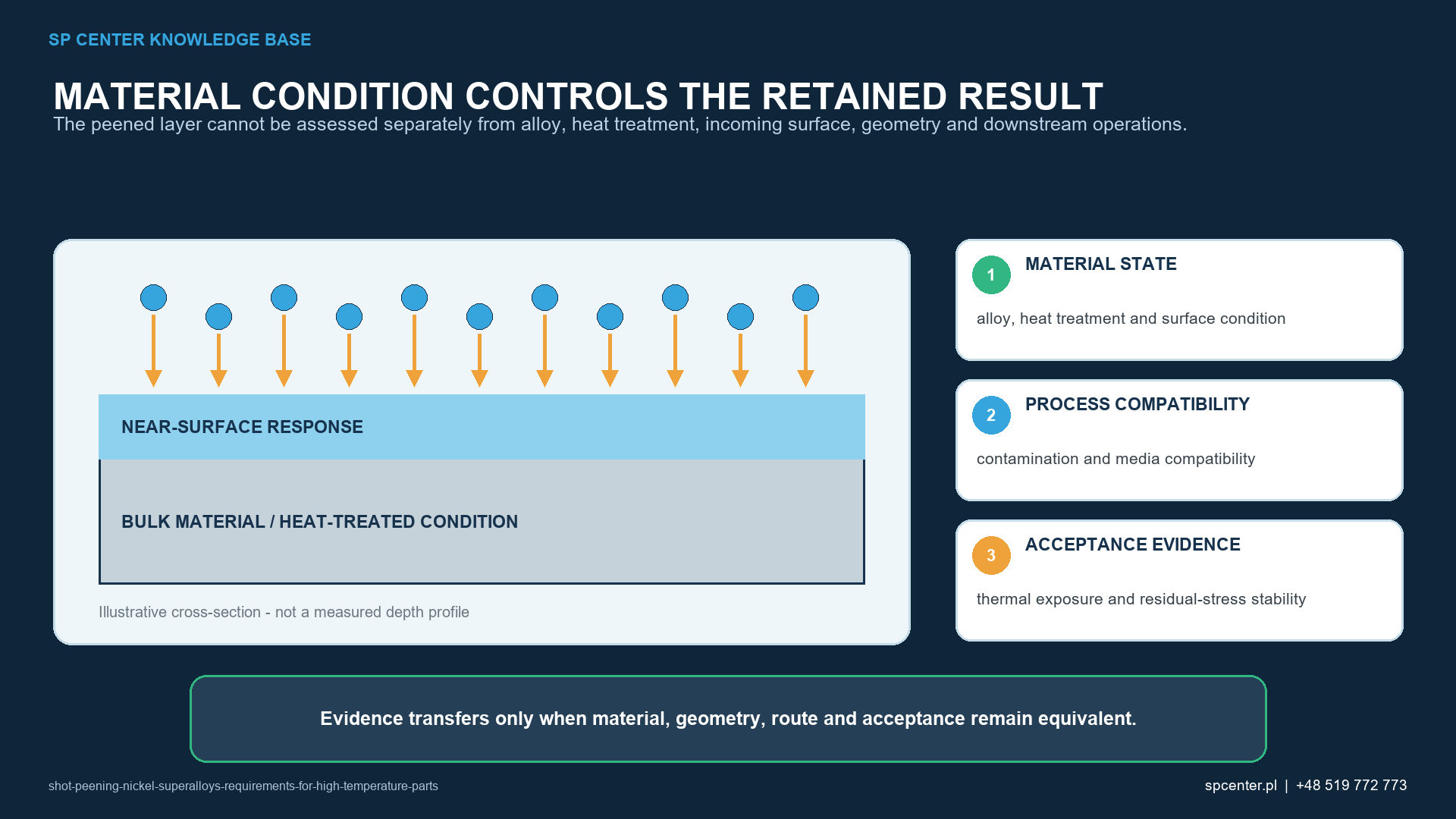
Wrought, cast, powder-metallurgy and additively manufactured nickel-base superalloys can have different grain structures, precipitate populations, defect distributions, surface conditions and heat-treatment responses. Even within one alloy designation, solution and ageing condition, manufacturing route and prior machining can change strength, ductility and the response to repeated impacts.
The process baseline must therefore identify the exact alloy and material condition. A result for IN718, ME3 or another studied alloy is evidence for that tested configuration, not a universal limit for all nickel-base superalloys.
| Part or surface | Service or manufacturing concern | Qualification focus |
|---|---|---|
| Disk bore, slot or attachment fillet | High cyclic stress, fretting and difficult access can make local coverage and surface damage critical | Representative geometry, access, transition zones and contact-surface limits |
| Blade airfoil or leading edge | Thin sections, profile, roughness and foreign-object-damage tolerance can control acceptance | Profile and edge protection, texture limits and application-specific performance evidence |
| Cooling or metering hole | Media entrapment, edge rounding, obstruction or altered flow area may be unacceptable | Explicit treatment or exclusion, masking, cleaning and inspection method |
| Seal land or mating surface | Roughness, form and transfer material can change sealing or contact behaviour | Treatment map, finish and dimensional limits, cleanliness requirement |
| Coated hot-section surface | Peening, coating deposition and diffusion heat treatment interact | Controlled process sequence and coating-specific qualification |
| Cast, wrought or additively manufactured feature | Defect population, grain structure, surface condition and response can differ | Exact alloy, product route, heat treatment and representative material condition |
Table 1. Component function and material route determine the treatment map and the evidence required.
Which high-temperature mechanisms must be considered?
Elevated temperature can relax or redistribute residual stress, while cyclic plasticity can produce additional relaxation. The rate and extent depend on alloy, microstructure, amount and depth of cold work, peak and dwell temperature, time, load ratio and number of cycles. Oxidation, hot corrosion, creep, fretting and thermomechanical fatigue may also control the surface response.
NASA work on shot-peened powder-metallurgy ME3 at room temperature and 704 °C, and published IN718 case studies after defined thermal exposures, illustrate that residual-stress retention is material- and condition-specific. Those studies support the need for representative validation; they do not create a generally safe temperature or a production recipe.
How should peening fit into the manufacturing sequence?
Machining, grinding, EDM, polishing, cleaning, peening, coating deposition, diffusion treatment and final finishing must be reviewed as one controlled route. Peening must not conceal cracks, laps, recast material, grinding damage or unacceptable casting or additive defects. Required defect removal and inspection come first unless the controlled process definition states otherwise.
A later polish or blend can remove part of the compressed layer. A later heat treatment can alter the residual-stress field and microstructure. Coating adhesion, coating stress and diffusion treatment can also depend on the incoming surface. The qualified sequence, permitted material removal and change authority must therefore be explicit.
How are media, contamination and impact conditions controlled?
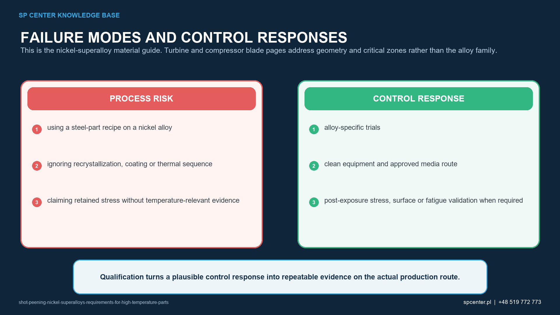
Media material, size, hardness, shape and condition interact with particle velocity, impact angle, media mass flow, exposure and surface strength. Steel media must not be treated as universally prohibited or universally acceptable for a nickel-base alloy. The governing drawing, specification and customer requirements decide what is authorized, while the qualification addresses transfer residue, cleanliness, corrosion or oxidation risk and compatibility with later coating or heat.
Broken or nonconforming particles, foreign-media carryover and an unstable operating mix can increase roughness, embed material or create local damage. Media segregation, replenishment, inspection and reaction limits must match the qualified process. Cleaning after peening must also remove free media without changing the accepted surface.
What do intensity and coverage prove?
| Control or evidence | What it establishes | What it does not establish alone |
|---|---|---|
| Media material, size, hardness, shape and operating condition | The particles delivered by the qualified system are within the authorized state | That transfer residue, roughness or microdamage is acceptable on the component |
| Air pressure or wheel speed, media mass flow, nozzle or wheel arrangement and traverse | The machine inputs and stream geometry match the controlled setup | The actual impact energy at every recessed or angled surface |
| Almen intensity from a valid saturation curve | The peening stream is verified in the approved Almen arrangement | Residual-stress depth, thermal stability or fatigue life of the nickel-alloy part |
| Component coverage | The required surface is covered by impact evidence using the approved method | That 200% exposure or additional time automatically improves performance |
| Surface, dimensional and cleanliness inspection | Roughness, profile, holes, edges and residue meet defined limits | The subsurface residual-stress field or its retention in service |
| XRD depth profile and representative thermal-mechanical testing | A specified alloy, condition and process can support the stated application claim | Transferability to another alloy, geometry, heat treatment or duty cycle |
Table 2. Process-control results, component acceptance and application performance are separate evidence layers.
SAE J442 and J443 govern the Almen tools and procedures used to determine and verify peening intensity; SAE J2277 addresses coverage determination. The complete controlled job requirements remain decisive. Neither a valid saturation curve nor complete coverage independently proves a target residual-stress depth, absence of microdamage, stable high-temperature performance or a fatigue-life multiplier.
How are thin edges, holes and precision surfaces protected?
Leading edges, thin airfoils, slot corners, cooling holes, seal lands and finished contact surfaces may be sensitive to rounding, distortion, roughness, blockage or embedded residue. The drawing or approved process plan must define treatment, exclusion and transition zones and the masking and cleaning method.
Where fixture contact or line-of-sight restricts access, a qualified multi-position route may be needed. The route must cover the required surface without uncontrolled cumulative exposure. Visual accessibility alone does not prove that particle angle and energy are representative of the qualified setup.
Which evidence supports a high-temperature application claim?
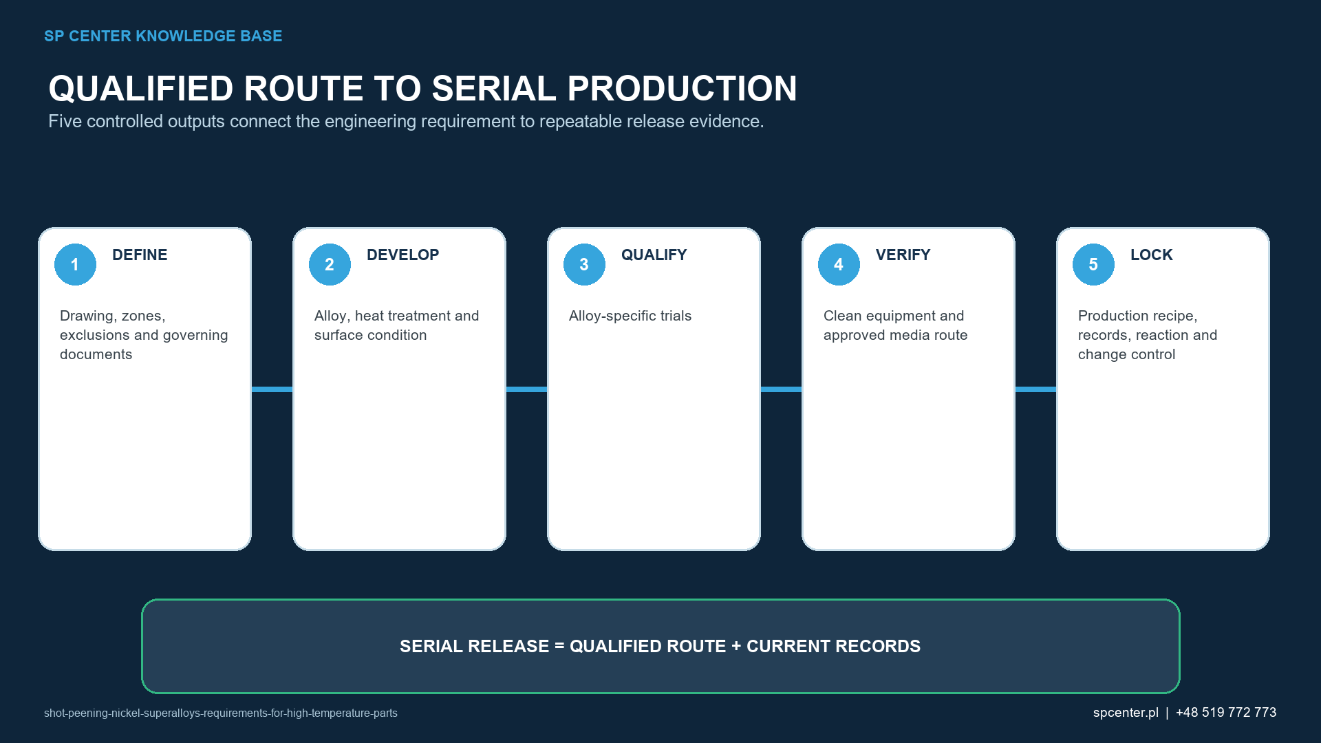
Routine release normally combines material and route traceability, verified equipment settings, media-control records, Almen intensity, coverage and the specified component inspections. A stronger application claim may require X-ray diffraction residual-stress profiles, controlled layer removal, representative geometry, thermal exposure and fatigue, dwell-fatigue, fretting or thermomechanical-fatigue testing.
SAE AS7045 classifies residual-stress measurement of metallic products and finished parts. The selected method, direction, location, depth increments, uncertainty and material-specific diffraction data must be suitable for the decision. XRD results on a convenient flat coupon do not automatically represent a blade root, slot or cooling-hole edge.
Which findings require containment and engineering disposition?
- The alloy, product route or heat-treatment condition differs from the qualified baseline.
- A crack, lap, inclusion-related indication, recast layer or unacceptable incoming defect is found.
- Media identity, operating mix, cleanliness or equipment settings are outside the authorized state.
- Coverage is incomplete or extends onto an excluded edge, hole or precision surface.
- Roughness, profile, dimensions, hole condition, edge radius or residue exceeds the limit.
- A coating, thermal exposure, blend, repair or process change was not included in qualification.
Stop processing and contain affected product from the last verified acceptable state. Preserve material, lot, equipment, media, fixture, Almen and inspection records and obtain the authorized disposition. Additional peening, polishing or cleaning is not an automatic correction.
What should an RFQ or qualification plan contain?
| RFQ or qualification input | Required detail | Why it matters |
|---|---|---|
| Material baseline | Exact alloy designation, melt or powder route, cast/wrought/additive condition, heat treatment and hardness if applicable | Nickel-base superalloys do not have one common peening response |
| Part definition | Controlled drawing, critical features, treatment and exclusion zones, transitions, holes, thin edges and datum surfaces | Prevents missed areas and damage to functionally sensitive geometry |
| Manufacturing route | Machining, grinding, EDM, polishing, cleaning, peening, coating, diffusion treatment and final finishing sequence | Later removal or heat can change the qualified surface state |
| Peening requirement | Governing specification, media, intensity range, coverage, equipment route and any customer source approval | Avoids importing a recipe from steel or another component |
| Acceptance limits | Roughness, profile, dimensions, edge condition, cleanliness, media residue, customer-specified inspections outside SP Center's service scope and records | Separates stream conformance from component acceptance |
| Service and validation claim | Temperature-time history, cyclic load, environment, coating system and performance evidence required | Defines whether thermal retention, oxidation, creep-fatigue or TMF must be represented |
Table 3. A usable request links material state, component function, process sequence and service evidence.
Also state part size and mass, quantity, packaging and handling limits, certificate content, source-approval status, inspection sampling and ownership of deviations and changes. If the governing specification, treatment map or high-temperature acceptance claim is unclear, obtain controlled clarification before processing.
Frequently asked questions
Can all nickel-base superalloys be shot peened with the same process?
No. Alloy, product route, grain structure, heat treatment, strength, surface condition, geometry and duty cycle all affect the permissible process window.
Is a steel-component shot-peening recipe suitable for a nickel-base superalloy?
Not without qualification. Media, intensity, exposure and acceptance limits must be established for the actual alloy, condition and feature.
Does Almen intensity measure residual stress in the part?
No. It verifies the peening stream in a standardized Almen arrangement. Component residual stress requires a suitable measurement method and qualified interpretation.
Will compressive residual stress remain stable at any turbine temperature?
No universal temperature can be stated. Retention depends on alloy, microstructure, cold work, temperature, time, cyclic loading and the rest of the manufacturing route.
Is steel shot always forbidden for nickel-base superalloys?
Not as a universal rule. Use only media authorized by the governing drawing, specification and customer requirements, and assess transfer residue and later thermal or coating operations.
Can shot peening repair cracks, laps or casting defects?
No. Rejectable defects require the specified inspection and authorized disposition before peening; the process must not be used to conceal them.
Should cooling holes be shot peened?
Only when the controlled definition states how their edges and internal surfaces are treated or excluded and how blockage, trapped media, geometry and cleanliness are verified.
What information is needed for a feasibility review?
Provide the alloy and condition, drawing and zones, manufacturing sequence, specification, media and intensity requirement, surface and dimensional limits, service temperature and required records.
Key takeaways
- Use the exact nickel-base alloy, product route and heat-treatment condition.
- Do not transfer a steel or another superalloy process without qualification.
- Treat residual-stress retention as a temperature-time-load question, not a single temperature limit.
- Control media compatibility, transfer residue, roughness and precision features.
- Separate Almen intensity and coverage from component integrity and service performance.
- Qualify the complete manufacturing sequence, including coatings and later thermal exposure.
Related SP Center guides
- Residual Stress Depth Profile After Shot Peening
- Shot Peening and Coatings
- Shot Peening Before or After Heat Treatment
- Surface Roughness After Shot Peening
Technical references
1. SAE J2441_202511: Shot Peening, stabilized November 2025
2. SAE AMS2430U: Shot Peening, revised April 2018
3. SAE AMS2431E: Peening Media, General Requirements, revised April 2023
4. SAE ARP7488: Peening Design and Process Control Guidelines, issued January 2018
5. SAE J442_202602: Tools for Peening Intensity Determination and Verification, revised February 2026
6. SAE J443_202512: Procedures for Determining and Verifying Peening Intensity, revised December 2025
7. SAE J2277_202301: Shot Peening Coverage Determination, revised January 2023
Standards and evidence note: The NASA studies concern specified alloys, specimen conditions and exposures. They support mechanism and validation planning, not a universal production parameter or temperature limit. Use the complete controlled drawing, specification and customer requirements.
Author: Paweł Kmieć
Discuss shot peening for a nickel-base superalloy part: +48 519 772 773 | [email protected]