


Qualify root attachments, platforms, airfoil zones, thin edges, cooling features and coating sequence as separate but connected blade risks
Turbine-blade shot peening is a feature-specific process for the exact drawing, alloy, heat-treatment or coating condition and service basis. A root attachment radius may need controlled peening while a datum face, thin trailing edge, cooling hole or coated airfoil needs protection or a different route. Correct Almen intensity alone does not prove local coverage, surface integrity or retained benefit at operating temperature.
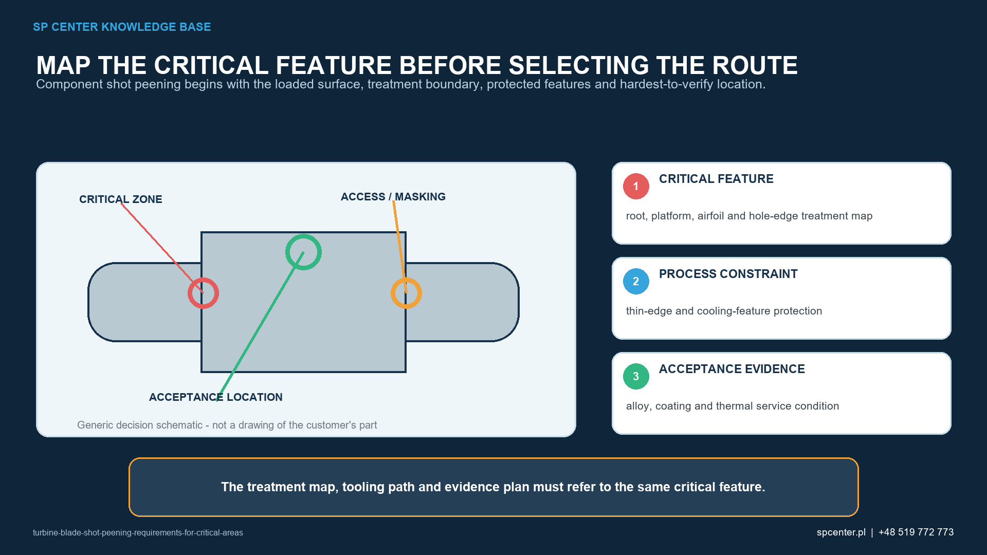
Which turbine-blade areas can be critical?
The treatment map can include fir-tree or dovetail attachments, root radii, platform fillets, selected airfoil regions, edges, tips or cooling-hole boundaries. It also identifies datums, contact faces, coating zones, holes, internal passages and surfaces that must remain untouched.
Do not copy a compressor-blade program or assume that the whole blade requires one intensity and exposure. Turbine blades can differ in material, crystal structure, coatings, wall thickness, cooling architecture and thermal-mechanical service.
| Blade feature | Primary risk | Control and acceptance question |
|---|---|---|
| Fir-tree, dovetail or other root attachment radius | High stress concentration, shadowing and line-of-sight variation | Is every specified radius reached at the qualified angle and exposure without an untreated line or local damage? |
| Root flank, contact face or datum | Fit, contact fatigue, fretting, dimensional or masking sensitivity | Does the drawing require treatment, protection or a controlled transition, and are fit surfaces still acceptable? |
| Platform and platform fillets | Complex junctions, rebound, mask boundaries and coating interfaces | Are all required fillets covered while adjacent protected surfaces and edges remain undamaged? |
| Airfoil pressure or suction surface | Thin section, aerodynamic contour, roughness, coating and local stress differences | Is treatment explicitly authorized and qualified for the actual airfoil zone and service condition? |
| Leading edge, trailing edge or tip | Erosion, rounding, distortion and sharp impact damage | Are edge dimensions, contour and surface integrity protected through a feature-specific process window? |
| Cooling hole, slot or internal passage | Media ingress, retained foreign material, blockage and edge damage | Are holes protected or treated as specified, then cleaned and verified by the invoked visual, dimensional or flow requirement? |
| Metallic, diffusion or thermal-barrier coating | Cracking, spallation, thickness change, contamination and sequence conflict | Is the coating state permitted during peening and is the complete peening–coating sequence qualified? |
Table 1. The drawing and approved engineering basis decide whether each feature is treated, protected or excluded.
Why are root attachments and platform fillets difficult?
Root attachments contain repeated radii, flanks, undercuts and contact surfaces. Line of sight, rebound and masking can create narrow untreated bands or local overexposure. A fixture must locate the blade repeatably without damaging a contact surface or blocking the stream.
Develop the path on the actual or authorized representative geometry. Challenge the least accessible radius, path start and stop, platform underside, transition zone and mask boundary. A robot program or nominal dwell time is not evidence of particle impact at the feature.
How are thin edges and airfoil contours protected?
Leading and trailing edges, tips and thin airfoil walls have low local stiffness and limited material reserve. Unsuitable media, velocity, angle or cumulative exposure can round, erode, fold or distort an edge and change aerodynamic contour. Treatment is applied only within a qualified, dimensionally safe domain.
Verify incoming edge condition and inspect after peening at the specified magnification and dimensional resolution. An acceptable average roughness does not cancel a sharp impression, crack, fold or local contour loss.
What controls cooling holes and internal passages?
Cooling holes and slots introduce edge sensitivity, shadowing and foreign-object risk. The drawing and process plan determine whether their edges are treated, masked or excluded. Plugs and masks are controlled tooling with approved material, fit, life and inspection.
After processing, remove media and masking residues through the authorized cleaning route. Verify hole condition, retained media, dimensions and flow only by the methods invoked for that blade. Rebound does not prove internal coverage, and a clean external surface does not prove an open internal passage.
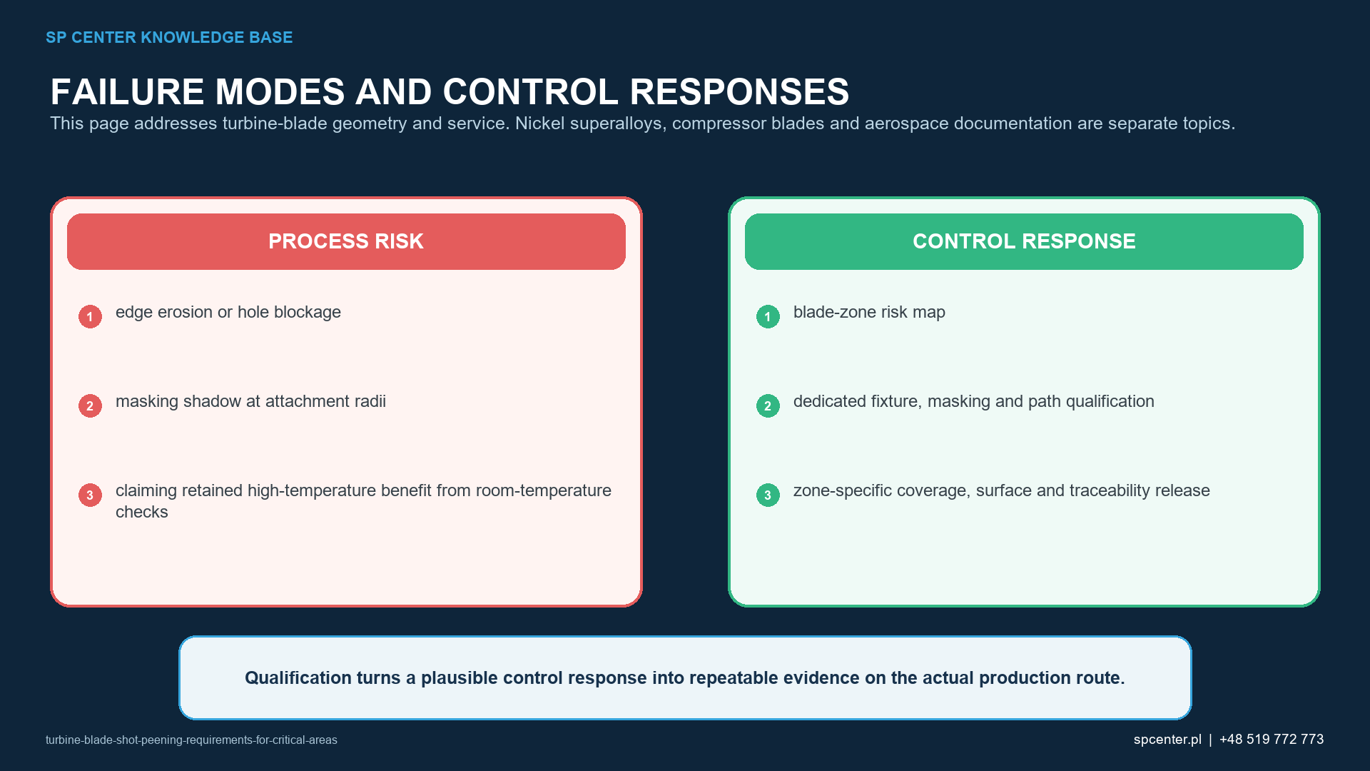
How does material and coating condition affect the route?
Nickel-base superalloys may be equiaxed, directionally solidified or single crystal; titanium alloys and other blade materials have different contamination, deformation and damage limits. Crystal orientation and anisotropy also complicate residual-stress measurement and transfer of coupon results.
Metallic bond coats, diffusion coatings and thermal-barrier coatings are not automatically compatible with peening. Define and control the permitted sequence among machining, heat treatment, peening, cleaning, coating and thermal exposure. Peening a coating or removing material after peening requires explicit authority and qualification.
Which process controls are qualified?
| Qualification element | Representative evidence | Failure that it prevents |
|---|---|---|
| Part and feature map | Controlled blade number and revision, alloy and condition, treatment, exclusion, transition and coating zones | Treating the wrong feature or applying a compressor-blade route to a turbine blade |
| Fixture and motion | Qualified orientation, supports, robot or machine path, speed, overlap and repeatable datum loading | Shadowing at roots, path drift, edge overexposure and fixture damage |
| Masking and hole protection | Approved material, location, fit, life, inspection and removal or cleaning method | Mask leakage, rebound, media trapping and blocked cooling features |
| Peening stream | Valid saturation curve and intensity, approved media, mass flow, pressure or wheel settings, distance and angle | Using pressure or nominal time as a substitute for qualified impact conditions |
| Coverage development | Direct or qualified indirect method at each critical feature and transition | Assuming root, underside or hole-edge coverage from an accessible witness area |
| Surface and dimensions | Defined inspection for cracks, folds, sharp impressions, roughness, edge contour, hole condition and critical dimensions | Releasing a blade that meets stream controls but has component damage |
| Performance basis | Residual-stress, thermal-relaxation, fatigue, fretting or oxidation evidence when a claim requires it | Applying room-temperature coupon results as a universal service-life factor |
Table 2. Feature-specific qualification links the physical stream to blade access, protection and acceptance.
Control the approved media material, size, hardness, shape and operating mix; intensity from a valid saturation curve; mass flow; pressure or wheel settings; distance, angle, path, speed, overlap and exposure. Maintain fixture, mask and program revisions with the same discipline as the machine settings.
How are intensity and coverage interpreted?
The Almen system characterizes a standardized process response. It does not measure residual stress in the blade and cannot represent every root radius, edge or cooling-hole boundary. Coverage is assessed on each specified surface by the approved direct or qualified indirect method.
Tracer or fluorescent methods are indirect tools that require qualification and correlation to the accepted coverage method for the actual surface. A visible tracer result does not by itself establish surface integrity, dimensions or performance.
What evidence supports room-temperature and service claims?
| Evidence level | What it can establish | What it cannot establish alone |
|---|---|---|
| Almen and machine records | The qualified stream and production configuration were verified | Local residual stress, critical-feature coverage or blade life |
| Coverage evidence | Specified surfaces show the required impact-impression coverage under the approved method | Absence of cracks, correct hole flow, coating durability or retained high-temperature benefit |
| Surface and dimensional inspection | Edges, holes, contours, masks, roughness and specified dimensions meet acceptance criteria | Residual-stress depth profile or fatigue performance |
| Residual-stress and material characterization | The defined material and feature developed the measured near-surface state | Stability after thermal exposure, dwell fatigue or another service cycle unless tested |
| Representative thermal-mechanical and fatigue evidence | A stated blade family, alloy, treatment and load-temperature route supports a defined performance claim | Transfer to another alloy, crystal orientation, coating, geometry or operating mission |
| Traceability and approval records | The released blade follows the current customer-approved process and deviations | Technical performance without the supporting process and component evidence |
Table 3. Production conformity and retained turbine-service performance are connected but distinct evidence levels.
Research on nickel-base superalloys shows that thermal exposure and cyclic or dwell loading can relax shot-peening residual stress. The magnitude and retained state depend on alloy, microstructure, cold work, temperature, time and loading. Therefore, do not use an as-peened room-temperature value as a universal service-life credit.
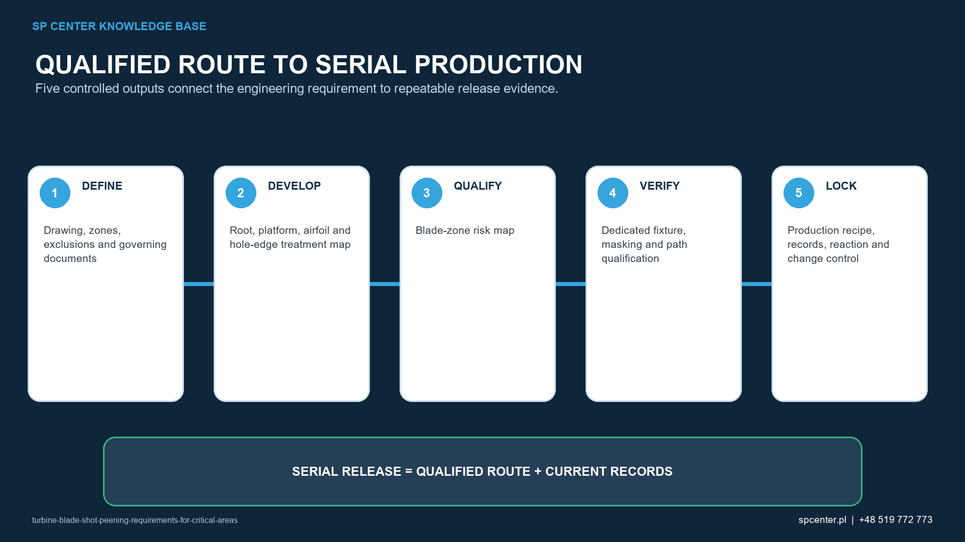
When performance credit is required, qualify the actual material and relevant feature after the full manufacturing route and representative thermomechanical exposure. Report measurement method, direction, depth, uncertainty, fatigue or dwell conditions and fracture origin.
How are nonconformance and reprocessing controlled?
Contain product after missed coverage, edge damage, media retention, mask leakage, coating damage, dimensional shift or an equipment alarm. Establish the last known conforming state and assess all affected serial or batch identities.
Reprocessing is not automatic. Cumulative exposure can increase cold work, roughness, distortion and damage. Obtain explicit authority, assess total exposure and repeat every required surface, hole, coating and dimensional check before release.
What belongs in the blade release record?
- Blade, serial or batch identity, drawing revision, alloy, heat treatment and coating condition.
- Approved feature map with treatment, exclusion, transition, edge and cooling-hole zones.
- Qualified machine, media, fixture, masks, plugs, path and program revisions.
- Current saturation, intensity, media-condition and alarm records.
- Feature-specific coverage, surface, edge, hole and dimensional acceptance.
- Cleaning, foreign-material and any required flow-verification records.
- Residual-stress or performance evidence when invoked.
- Changes, deviations, customer approvals and final release traceability.
Frequently asked questions
Should the entire turbine blade be shot peened?
Only if the controlled drawing and approved process require it. Roots, platforms, airfoils, edges, cooling features and coated zones can need different treatment, protection or exclusion.
Can a coated turbine blade be shot peened?
Only when the coating type, condition and peening sequence are explicitly permitted and qualified. Metallic, diffusion and thermal-barrier systems can respond differently to impact, masking, cleaning and later heat exposure.
How are cooling holes protected during shot peening?
Use the approved masking, plugging, orientation, path and cleaning route. Release follows the invoked inspection or flow requirement; visual absence of loose media alone may be insufficient.
Does correct Almen intensity prove root-radius coverage?
No. Almen intensity verifies a standardized stream response. Access and coverage at each specified root radius, underside and transition need separate evidence.
Can shot peening damage a thin trailing edge?
Yes, if media, energy, angle or exposure is unsuitable. Edge rounding, erosion, distortion, sharp impressions and folding require feature-specific limits and inspection.
Does room-temperature residual stress prove benefit in turbine service?
No. Nickel-superalloy studies show that thermal exposure and cyclic or dwell loading can relax peening-induced residual stress. Retained benefit must be validated for the relevant alloy, temperature, time and loading.
Is a single-crystal blade evaluated like an equiaxed alloy blade?
No automatic equivalence exists. Crystal orientation, anisotropy, microstructure, coating and heat exposure can affect deformation and residual-stress measurement. Use a material- and orientation-specific qualification basis.
Can shot peening repair a cracked turbine blade or damaged cooling hole?
No. Stop and use the authorized inspection, repair and design-disposition route. Peening must not be used to conceal cracks, loss of section, coating failure or unacceptable geometry.
Key takeaways
- Treat the blade as a map of different features, not one uniform surface.
- Qualify the least accessible root radius and the most damage-sensitive edge.
- Control cooling-hole protection, cleaning and verification as part of peening.
- Do not assume that coatings or single-crystal alloys follow a generic route.
- Separate Almen intensity, coverage, surface acceptance and service performance.
- Validate retained benefit after relevant thermal-mechanical exposure when claimed.
Related SP Center guides
- Shot Peening Nickel Superalloys
- Compressor Blade Shot Peening
- Aerospace Shot Peening
- Shot Peening Coverage Inspection
Technical sources
1. SAE J2441_202511: Shot Peening, stabilized November 2025
2. SAE AMS2430U: Shot Peening, revised April 2018
3. SAE AMS2432E: Shot Peening, Computer Monitored, revised October 2022
4. SAE ARP7488: Peening Design and Process Control Guidelines, issued January 2018
5. SAE J2277_202301: Shot Peening Coverage Determination, revised January 2023
Standards note: Apply the complete drawing, customer flow-down and invoked specification revisions. This guide does not establish a universal blade treatment map or service-life factor.
Author: Paweł Kmieć
Discuss controlled turbine-blade shot peening: +48 519 772 773 | [email protected]