


How to control attachment roots, fillets, airfoil surfaces, thin edges, fixture presentation, coverage and aerospace release evidence
Compressor-blade shot peening must reproduce the drawing-defined treatment on attachment roots, fillets, selected airfoil surfaces or other specified features without damaging leading or trailing edges, changing thin sections, blocking small features or compromising root and profile dimensions. The qualified route combines material and incoming condition, treatment boundaries, fixture datums, stream orientation, media, Almen intensity, coverage, inspection, traceability and change control.
Why are compressor blades difficult to shot peen?
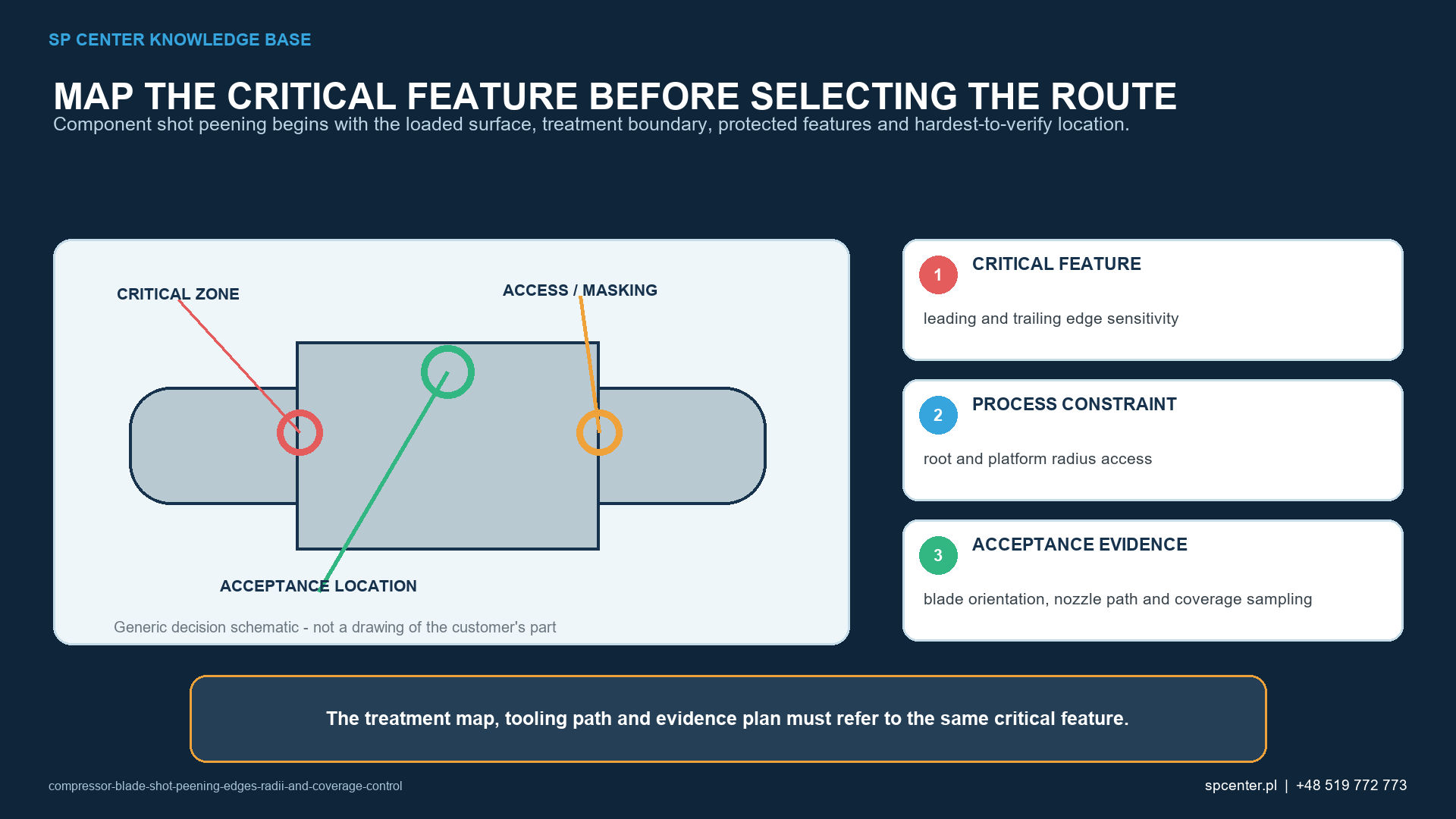
A blade combines highly curved surfaces, attachment geometry, varying wall thickness, thin edges and aerodynamic profile requirements. The same fixed stream can strike one surface normally, graze another and miss a recessed fillet. Rebound from the root or fixture can change local impact conditions, while long dwell on an exposed airfoil can increase roughness or distortion.
The name “compressor blade” is not a process definition. Rotor blades, stator vanes, variable vanes and integrated structures can have different materials, loads, surfaces, coatings, repair rules and customer approvals. Use the exact part number, drawing, revision and configuration.
Which blade zones require separate review?
| Blade feature | Primary risk | Required control question |
|---|---|---|
| Attachment root and flank | Shadowing, rebound, media retention, dimensional or contact-surface change | Which faces are treated, protected and inspected, and how is the root presented? |
| Root-to-airfoil fillet | High fatigue sensitivity with changing impact angle | Does the nozzle or wheel path reach the full radius with representative coverage evidence? |
| Airfoil surface | Roughness, profile change, local overexposure or interaction with later coating | Is the surface included by drawing and what aerodynamic or coating acceptance applies? |
| Leading and trailing edge | Edge breakdown, local deformation, excessive roughness or notch creation | Is the edge treated, transitioned, masked or excluded, and what damage limit applies? |
| Tip or thin section | Distortion and unbalanced residual-stress or plastic-strain field | How are support, balanced sequence, exposure and dimensional checks qualified? |
| Small hole, slot or damping feature | Media entrapment, blockage, inaccessible shadowed surface or impact on function | Is treatment required, feasible and verifiable, and how is retained media removed? |
Table 1. Each feature has a different combination of access, damage and acceptance risk.
How should treatment and exclusion zones be defined?
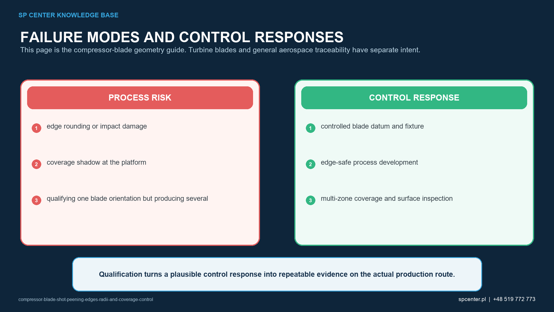
The drawing or controlled repair instruction should identify every surface to peen, exclude or protect and define transitions. The treatment map must resolve root flanks, load-bearing contact faces, fillets, platform areas where present, airfoil pressure and suction sides, leading and trailing edges, tip, identification marks, holes and slots.
Do not infer boundaries from a photograph, old part or another blade family. If a note conflicts with a marked zone or the repair document conflicts with the production drawing, stop the affected work and obtain controlled clarification from the responsible authority.
How do material and incoming condition affect the route?
Compressor blades can use titanium, nickel, stainless or other alloys and conditions. Exact alloy, product route, heat treatment, coating or diffusion layer, prior machining, blending, polishing, service exposure and cleaning state affect damage sensitivity, media restrictions, roughness and residual-stress stability.
Incoming cracks, impact damage, corrosion, fretting, overheating, grinding damage or an unapproved blend must be evaluated before peening. Shot peening must not be used to hide an indication or replace an authorized repair disposition.
How should the blade be fixtured?
Fixture datums should locate the blade without damaging contact surfaces and should reproduce position and orientation from part to part. Clamp force, support and exposure balance must control movement and distortion. Replaceable protectors, masks and shields need defined identity, condition and installation checks.
The fixture can shadow a required surface or generate rebound. Qualification should use the intended production fixture and loading direction. If multiple blades are processed together, assess stream interaction, pitch, shielding and first-to-last position rather than assuming equivalent exposure.
How are Almen intensity and stream geometry qualified?
Use the complete Almen range, strip designation, notation and procedure from the governing requirement. Holder locations and orientation should represent the qualified stream and critical directions as required, but the Almen strip does not duplicate the blade’s curvature, stiffness or residual-stress response.
Pressure, air flow, media mass flow, wheel speed, nozzle or wheel distance, angle, part motion and exposure are controlled inputs—not substitutes for Almen intensity. Changing one can alter the stream pattern and local blade response even when a nominal setting appears similar.
How is coverage demonstrated on roots and fillets?
Coverage is the degree to which the specified blade surface shows impact evidence under the approved inspection method. One hundred percent coverage means no visible unpeened area remains in the required zone under the defined conditions. Inspect the actual root flanks, radii, transition boundaries and other specified areas rather than only the most accessible face.
Lighting, magnification, surface finish, viewing angle and scanning sequence should be controlled. Fluorescent tracer or another indirect method can support difficult geometry only when approved, qualified and correlated. Additional time cannot repair a shadowed area and can overexpose adjacent thin edges.
How are leading and trailing edges protected?
First determine whether each edge is treated, transitioned or excluded. Where protection is required, qualify mask material, thickness, fit, boundary, durability and removal. A hard mask can create rebound; a worn or lifted mask can expose the edge; an excessive overlap can leave a prohibited untreated zone.
Inspection should address edge radius or profile, nicks, rollover, roughness, cracks, local deformation and mask marks according to the drawing or repair instruction. There is no universal instruction to mask every blade edge.
How should distortion and dimensions be controlled?
Thin sections can respond to unbalanced plastic strain and residual stress. Development should consider support, sequence, opposing-side balance, intensity, media, exposure and fixture release. Dimensional checks can include root features, airfoil profile, chord, twist, tip or other drawing characteristics when invoked.
A blade that passes coverage but fails profile or edge acceptance is not conforming. If the process is changed to correct distortion, repeat the required qualification review rather than adjusting settings informally.
What evidence belongs to qualification?
| Evidence layer | Representative evidence | Decision supported |
|---|---|---|
| Requirement maturity | Current drawing, revision, material and condition, treatment map, exclusions, specification hierarchy and repair status | The correct blade configuration and authority are understood |
| Peening-stream qualification | Media, Almen range and strip designation, saturation or verification, equipment, holder positions and monitored inputs | The qualified stream and configuration are established |
| Geometry and coverage qualification | Representative blade or approved surrogate, fixture, motion, boundaries, lighting, magnification and any correlated indirect method | Every required blade surface can receive and demonstrate complete treatment |
| Surface and dimensional acceptance | Edges, profile, root dimensions, roughness, prohibited damage, cleanliness and retained media when invoked | The actual blade remains within functional acceptance |
| Part-level validation | Residual-stress profile, fatigue, distortion or other customer-required evidence | The route supports the authorized component objective within its basis |
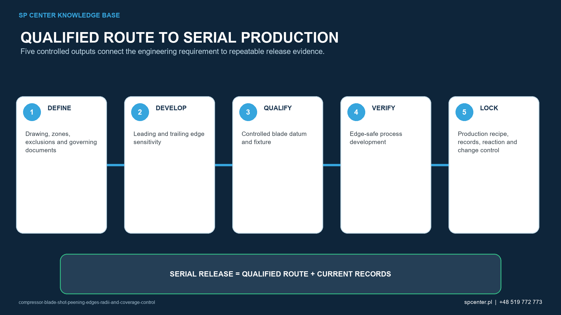
| Production and release | Part or serial traceability, programme, fixture, media, Almen, coverage, inspection, deviations and authorized release | The serial blade was processed under the approved route |
Table 2. Qualification separates stream, geometry, surface and component-level evidence.
What should be controlled in every batch?
| Production checkpoint | What to verify | Typical stop condition |
|---|---|---|
| Before loading | Part number, drawing revision, material condition, repair or blend status, cleanliness and incoming inspection | Unknown configuration, unapproved repair or unresolved surface indication |
| Fixture and programme | Correct fixture identity, datum contact, orientation, recipe revision, nozzle or wheel setup and masking | Wrong or damaged fixture, uncontrolled programme or unclear boundary |
| Media and intensity | Approved media identity and condition plus required Almen evidence | Nonconforming media, failed verification or expired measuring equipment |
| During the cycle | Part and stream motion, monitored inputs, interruptions, alarms and media feed | Unreconstructable exposure, motion fault or limit excursion |
| After peening | Coverage, edge and surface condition, root and profile dimensions, retained media and cleanliness as invoked | Untreated zone, damage, distortion, blockage or missing evidence |
| Release | Traceability, records, deviations, approved dispositions, customer forms and release authority | Open nonconformance, incomplete record or unauthorized change |
Table 3. Batch release requires both a conforming blade and a complete, authorized evidence record.
How should repairs and re-peening be handled?
A repair can change material thickness, edge profile, surface finish, local stress concentration and previous peening history. Use only the authorized repair document and confirm whether the area must be re-peened, which route applies, how prior exposure is considered and which dimensional, surface and customer-specified inspections outside SP Center's service scope checks are required.
Do not add an extra full cycle to “ensure coverage” after an interruption or blend. Reprocessing can increase roughness, distortion and surface damage and may exceed the qualified basis. Preserve part status and obtain an approved disposition.
Which records support aerospace traceability?
- Part number, drawing and repair revision, serial or lot identity and quantity.
- Material and condition plus incoming and repair status when required.
- Processing site, machine, programme, fixture, masking and operator identity.
- Media identity and condition evidence required by the route.
- Almen determination or verification and coverage records.
- Edge, surface, dimensional, cleanliness and retained-media results when invoked.
- Interruptions, alarms, deviations, approved dispositions and change status.
- Customer forms, certificate and authorized final release.
Frequently asked questions
Which parts of a compressor blade are shot peened?
Only the drawing-defined surfaces. Depending on design, these can include attachment roots, flanks, fillets, selected airfoil areas, tips or other features. Leading and trailing edges or functional contact surfaces may be treated, transitioned, protected or excluded.
Why are leading and trailing edges sensitive?
Their small local thickness and curvature can make them vulnerable to edge breakdown, roughness, deformation or notch creation. Exact treatment status, support, impact conditions and acceptance criteria must be qualified.
Does a conforming Almen result prove the blade is fully covered?
No. Almen evidence verifies the peening stream under the test arrangement. Coverage is accepted on every specified blade surface using the approved method and qualified geometry route.
Can fluorescent tracer be used on compressor blades?
Only when the governing route approves it and the method is qualified and correlated to the applicable direct coverage basis. It remains an indirect aid and does not replace surface-damage inspection.
Can shot peening distort a compressor blade?
Yes, particularly on thin, asymmetric or unsupported sections and under unbalanced exposure. Fixture support, sequence, process window and dimensional or profile checks must address the risk.
Can a blended or repaired blade be peened again?
Only under an authorized repair and re-peening route. Confirm remaining geometry, defect removal, treatment boundaries, prior exposure, qualification and customer approval; do not improvise an extra cycle.
Is Nadcap always required for compressor blade shot peening?
Only when the customer, contract or programme invokes it. Verify the exact processing site’s current Surface Enhancement scope and any separate customer approved-source requirement.
What information is needed for a quotation?
Provide the current drawing and repair status, blade material and condition, treatment and exclusion map, complete intensity and coverage requirements, media restrictions, dimensions, quantity, serial traceability, qualification, inspections, records and target milestones.
Key takeaways
- Treat only drawing-defined blade surfaces and protect or transition the rest as specified.
- Qualify the exact material, repair state, fixture and production orientation.
- Keep Almen intensity separate from coverage and component acceptance.
- Inspect difficult roots and fillets with an approved, representative method.
- Control thin-edge damage, roughness, profile and distortion.
- Do not re-peen or change the route without authorized review.
Related SP Center guides
Technical references
1. SAE AMS2430U: Shot Peening, revised April 2018
2. SAE AMS2432E: Shot Peening, Computer Monitored, revised October 2022
3. SAE ARP7488: Peening Design and Process Control Guidelines, issued January 2018
4. SAE J442_202602: Tools for Peening Intensity Determination and Verification, revised February 2026
5. SAE J443_202512: Procedures for Determining and Verifying Peening Intensity, revised December 2025
6. SAE J2277_202301: Shot Peening Coverage Determination, revised January 2023
Standards note: The complete revisions, drawing, repair data and customer requirements invoked by the contract govern.
Author: Paweł Kmieć
Discuss a compressor-blade requirement: +48 519 772 773 | [email protected]