


Qualify the delivery device, centring and motion for the full depth and circumference, then prove coverage, dimensions and media removal inside the actual geometry
Shot peening a bore or internal surface requires more than placing a small nozzle at the opening. The stream must reach the complete specified length and circumference with controlled energy, angle, media flow and overlap. Diameter, length-to-diameter ratio, shoulders, blind ends, cross-holes and return flow can create shadowing or local overexposure. If delivery and inspection cannot be demonstrated, the internal route is not qualified.
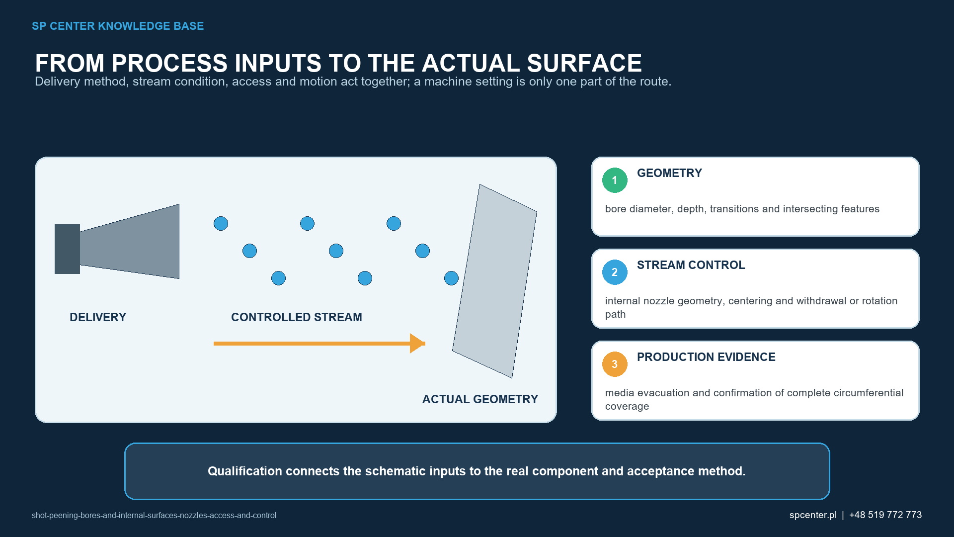
Which geometric features control feasibility?
The accessible opening does not represent the complete internal surface. Radial clearance can change along a tapered or stepped bore; a shoulder can block line-of-sight; a cross-hole can divert media; and a blind end can cause rebound and dwell. The process plan must map each feature and the required treatment boundary.
| Internal feature | Dominant risk | Qualification focus |
|---|---|---|
| Straight through-bore | Off-centre lance and uneven circumferential exposure | Centreline control, full-length traverse, rotation and overlap |
| High length-to-diameter bore | Energy loss, media return interference and limited inspection | Delivery stability, exhaust path, worst-depth evidence and cleaning |
| Blind bore | Dwell at the end, rebound and retained media | Defined turnaround, blind-end acceptance and verified media removal |
| Shoulder or counterbore | Shadowed corner and abrupt distance change | Separate passes or nozzle geometry, transition coverage and damage limits |
| Cross-hole or intersecting passage | Edge damage, escape path and local overexposure | Treatment boundary, motion timing, edge inspection and cleaning |
| Small or curved internal passage | Nozzle cannot maintain qualified orientation or free flow | Feasibility demonstration; reject the route if delivery and inspection cannot be controlled |
Table 1. Internal geometry determines the delivery, motion, inspection and cleaning strategy.
Which delivery devices are used for internal peening?
Depending on geometry and qualified equipment, the stream may be delivered by a straight or angled nozzle, an internal lance, a rotating lance or a deflector arrangement. These options are not interchangeable. A deflector changes stream direction and footprint and can wear rapidly; a rotating device adds speed, runout and synchronization controls.
The selected device must pass through the opening with adequate clearance, maintain orientation, avoid contact with the component and allow media and air to return without choking the flow. Its identity, critical dimensions, wear condition and replacement limit should be controlled.
How are centring, rotation and axial traverse qualified?
An off-centre lance changes stand-off and impact conditions around the circumference. Fixtures therefore need repeatable datums and support without distorting the bore. The process must define which element rotates, the direction and speed, axial start and stop points, traverse rate, number of passes and overlap.
Acceleration, turnaround and withdrawal can create unintended dwell, especially near a blind end or shoulder. Qualification should challenge the deepest or most shadowed location and the region most vulnerable to overexposure, not only the bore entrance.
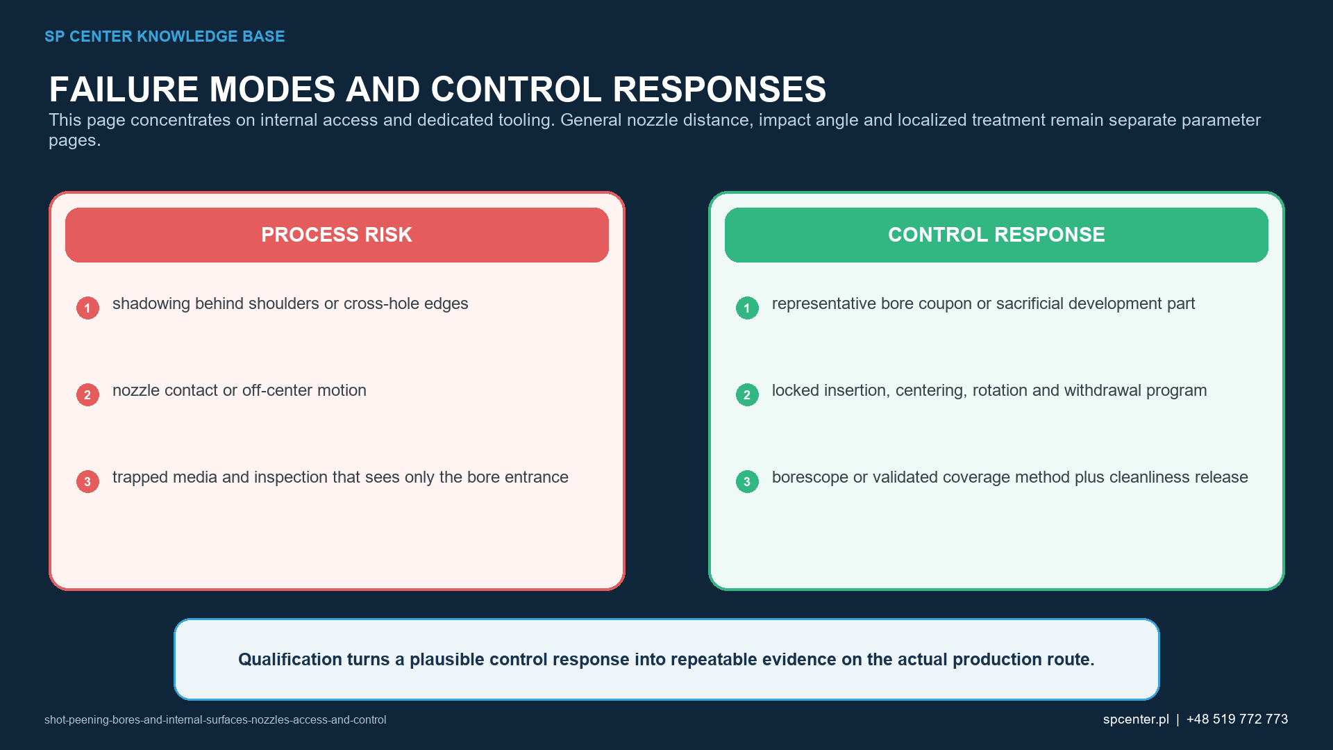
How is internal intensity verified?
Almen intensity characterizes the peening stream in a standardized response system, but internal verification requires a qualified fixture and representative stream relationship. A strip mounted outside the bore, at another distance or at a convenient angle is not automatically equivalent to the internal target.
The verification plan should state strip type, holder geometry, location, orientation, saturation procedure and relationship to the production configuration. If direct internal placement is impossible, any surrogate must be justified and kept within the qualified equipment, nozzle, media, flow and motion baseline.
How can coverage be assessed in a difficult-to-see bore?
Coverage is the extent of impact evidence on the specified surface; it is not a coating rate and not proof of intensity. Direct viewing may require controlled lighting, magnification or a borescope. Image quality, focus, viewing angle, contamination and surface texture limit what the method can detect.
Tracer or fluorescent methods are indirect controls. They may support inspection only when approved, qualified and correlated to the applicable coverage method for the actual geometry and process. Representative coupons, replicas or sectioned development parts can support qualification, but they do not automatically replace production acceptance.
Which evidence supports release?
| Evidence | Question answered | What it cannot prove alone |
|---|---|---|
| Lance, nozzle or deflector inspection | Is the delivery hardware within its approved condition? | Was the entire bore covered at the required process condition? |
| Almen intensity and saturation at qualified verification locations | Is the peening stream reproducible in the approved test arrangement? | Is intensity uniform at every bore depth and circumference? |
| Component coverage or correlated indirect method | Does the specified internal zone show the required impact evidence? | Are roughness, diameter, cleanliness or residual stress acceptable? |
| Borescope and surface inspection | Are visible damage, masking loss and retained media absent within method capability? | Does appearance quantify stress depth or fatigue life? |
| Dimensional and roughness measurement | Do diameter, form, profile and surface limits pass at stated locations? | Was the stream stable during every production cycle? |
| Residual-stress or representative fatigue evidence | Does the qualified configuration address an application-specific claim? | Can another bore size, nozzle or material use the result without review? |
Table 2. Internal stream control, coverage, surface condition, dimensions, cleaning and performance are different release questions.
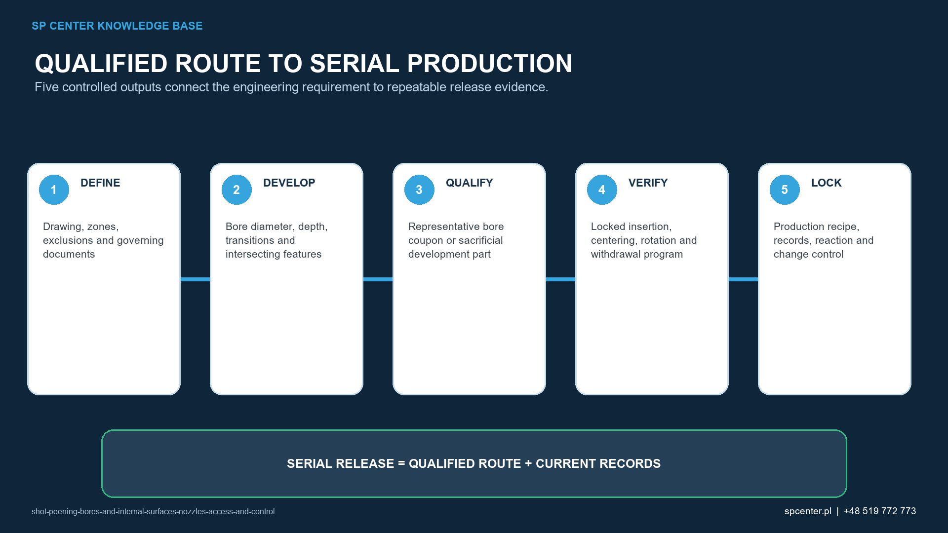
How are media retention and contamination controlled?
Blind ends, grooves, cross-holes and connected oil passages can retain media or fragments. Cleaning should use a validated orientation and method and should not drive media deeper into another passage. Final inspection must cover every escape and collection location identified in the risk review.
Media type also matters. Transfer or embedment may be unacceptable for the component material, coating, lubricant or cleanliness class. A clear bore entrance is not proof that the deepest pocket is clean.
Which changes require review or containment?
- Lance, nozzle or deflector identity, dimensions, wear limit or material changes.
- Bore diameter, depth, shoulder, cross-hole, blind-end or tolerance changes.
- Fixture centring, rotation, traverse, turnaround, pass count or program changes.
- Media type, size, condition, flow, air pressure or separator condition changes outside the baseline.
- Coverage, borescope, dimensional, roughness or cleaning method changes.
- Media is found after cleaning or an internal zone cannot be inspected as qualified.
Stop processing and contain parts from the last verified acceptable condition. Preserve the delivery hardware, media, program, fixture and inspection evidence. Repeating exposure is not an automatic correction because the inaccessible zone and the previously treated region may receive different cumulative doses.
What should an RFQ or drawing define?
| RFQ input | Why it matters | Risk prevented |
|---|---|---|
| Bore diameter, length and tolerance | Sets lance clearance, access, motion and measurement capability | Equipment is selected from an incomplete envelope |
| Blind ends, shoulders, grooves and cross-holes | Identifies shadowing, rebound, edge and media-retention risks | Critical transitions are omitted from qualification |
| Treatment and exclusion limits | Defines axial and circumferential start-stop boundaries | Overspray reaches seats, threads or sealing lands |
| Material, heat treatment and incoming finish | Controls damage sensitivity and final-surface requirements | A bore route is copied between unlike conditions |
| Intensity, coverage and component limits | Separates stream control from internal-surface acceptance | A remote Almen result becomes the only release criterion |
| Cleaning, inspection and traceability | Defines evidence for retained media and difficult-to-see areas | Product is released with hidden debris or an unverifiable zone |
Table 3. A sectioned geometry and explicit internal acceptance criteria are essential for feasibility and quotation.
Also provide overall part size and mass, handling restrictions, batch quantity, cleanliness and packaging, required certificates and approval authority. Processing should wait for controlled clarification when the internal boundary or inspection method is missing.
Frequently asked questions
Can every bore be shot peened?
No. The delivery device, media flow, motion, coverage and inspection must be controllable. Some small, curved, blind or obstructed passages are not feasible with the available process.
Does an external Almen test prove intensity inside a bore?
No. Intensity verification must use the qualified arrangement and locations defined for the process. A remote external test cannot be assumed equivalent to the internal stream.
How is coverage checked inside a bore?
Use the method approved by the governing requirement and qualification. Direct visual inspection, borescope inspection, qualified tracer methods or representative destructive evidence may be used when properly correlated.
Can a fluorescent tracer replace visual coverage inspection?
Only when the method is approved, qualified and correlated to the applicable coverage method for the actual geometry and process.
How is a blind end controlled?
The route needs a defined approach, turnaround and withdrawal motion, local acceptance and verified cleaning so dwell, rebound and retained media remain controlled.
Can a worn deflector change the process?
Yes. Wear, erosion, blockage or movement can change direction, footprint and energy. Inspection and replacement limits must be part of the approved baseline.
Does complete coverage prove the bore is acceptable?
No. Diameter, form, roughness, edge condition, cleanliness and any residual-stress or fatigue requirement remain separate.
What information does SP Center need to assess an internal surface?
Provide a sectioned drawing or model, diameter and depth, all shoulders and cross-holes, material, treatment map, specifications, limits, quantity and required inspection records.
Key takeaways
- Assess the full bore geometry, not only the opening.
- Qualify the exact lance, nozzle or deflector and its wear limit.
- Control centring, rotation, traverse, overlap and turnaround as one motion system.
- Do not infer internal intensity from an unrelated external Almen location.
- Use only approved and correlated coverage methods for inaccessible surfaces.
- Verify dimensions, roughness and complete media removal independently.
Related SP Center guides
- Nozzle Distance in Shot Peening
- Impact Angle in Shot Peening
- Shot Peening Coverage Inspection
- Shot Peening Fixtures
Technical references
1. SAE J2441_202511: Shot Peening, stabilized November 2025
2. SAE AMS2430U: Shot Peening, revised April 2018
3. SAE AMS2432E: Shot Peening, Computer Monitored, revised October 2022
4. SAE ARP7488: Peening Design and Process Control Guidelines, issued January 2018
5. SAE J442_202602: Tools for Peening Intensity Determination and Verification, revised February 2026
6. SAE J443_202512: Procedures for Determining and Verifying Peening Intensity, revised December 2025
7. SAE J2277_202301: Shot Peening Coverage Determination, revised January 2023
Standards note: Use the complete revisions invoked by the drawing, contract and customer flow-down. No cited standard makes every bore feasible or validates an uncorrelated internal surrogate.
Author: Paweł Kmieć
Discuss peening a bore or internal surface: +48 519 772 773 | [email protected]