


Define nozzle datum, measurement direction and tolerance, then qualify stand-off together with angle, footprint, motion and the complete pneumatic stream
Nozzle stand-off distance changes stream spread, local footprint and particle behaviour between the nozzle exit and component. It can therefore affect local intensity, coverage rate, access and repeatability. A valid distance is not a universal setting: it belongs to a qualified combination of nozzle, air supply, media mass flow, media, angle, motion, tooling and component geometry.
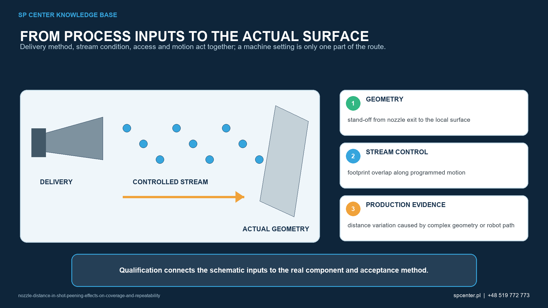
How does stand-off distance affect the peening stream?
| Distance-related change | Possible process effect | Why no universal rule applies |
|---|---|---|
| Shorter stand-off | Narrower footprint and higher local exposure can occur | Nozzle design, particle acceleration, angle and media flow can change the response |
| Longer stand-off | Broader footprint, more dispersion and lower particle energy can occur | Airflow, particle size and density determine velocity loss and stream spread |
| Changing surface curvature | Distance and incidence angle vary along one programmed path | The same robot coordinates do not create the same local geometry |
| Nozzle wear or replacement | Exit geometry, stream origin and footprint can shift | Nominal tool position does not prove the physical stream stayed equivalent |
| Fixture or part-location error | The whole path can move relative to treatment boundaries | A correct programme can run on an incorrectly located component |
Table 1. Distance effects are tendencies that require configuration-specific qualification, not fixed laws for every machine.
After particles leave a pneumatic nozzle, the stream can diverge and interact with the surrounding air. Particle size, density and shape influence how readily velocity and direction change. A shorter or longer distance must therefore be evaluated with the actual nozzle and operating media rather than by copying a value from another process.
Distance also changes the geometric footprint. A narrow footprint may increase sensitivity to path error and overlap; a broad footprint may reach excluded zones or lose useful definition. Neither condition proves the specified coverage.
How should nozzle distance be defined?
| Control element | Definition required | Verification |
|---|---|---|
| Distance datum | Nozzle exit plane or another approved physical datum | Drawing, setup instruction or validated digital model |
| Measurement direction | Along nozzle axis, local normal or expressly defined construction | Repeatable setup method and inspection aid |
| Tolerance | Permitted range at relevant path locations | Setup check, robot or fixture verification and reaction limit |
| Motion and overlap | Speed, index, pass sequence and treatment boundaries | Footprint or coverage mapping on representative geometry |
| Tool and part location | Nozzle TCP, fixture datum and component seating | Calibration, reference check and first-cycle confirmation |
| Nozzle condition | Type, bore, wear limit, holder and replacement rule | Periodic inspection and post-change verification |
Table 2. A numerical value is repeatable only after its origin, direction, tolerance and verification method are defined.
“Distance to the part” is ambiguous on a fillet, bore, curved airfoil or changing wall. The process document should identify the nozzle datum and the corresponding point or surface construction on the component. It should also define how the value is checked before and during production.
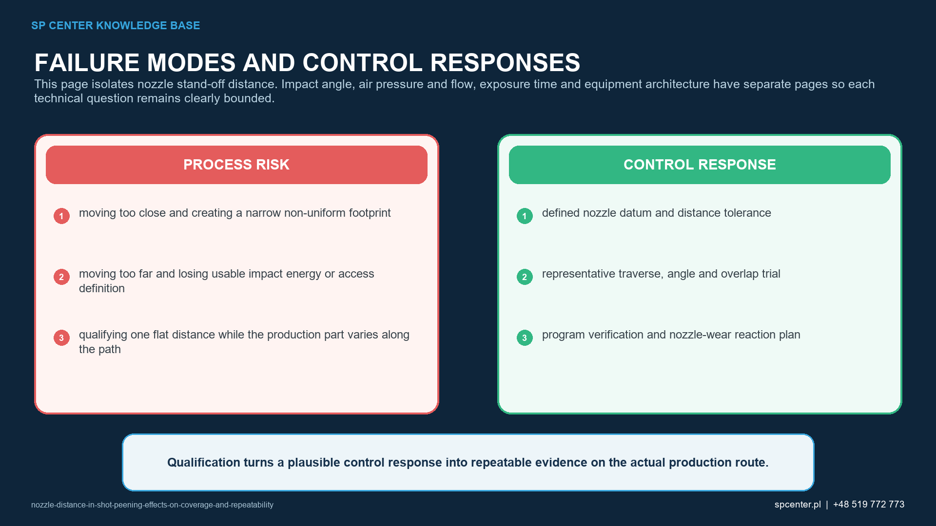
How do angle, traverse and overlap interact with distance?
Changing stand-off changes the footprint width and energy distribution, so the previously qualified traverse spacing or index may no longer create the same overlap. Incidence angle can also change at the same time, especially on curved geometry or when the robot path is offset without recalculation.
Qualification maps the complete path: treatment boundaries, least-accessible features, start and stop zones, reversals, acceleration segments and possible shadowing. It uses the production fixture, component orientation, motion and nozzle holder.
How is stand-off qualified?
- Freeze drawing, treatment map, governing requirements and the complete equipment configuration.
- Define nozzle type, physical datum, measurement direction, nominal distance and tolerance.
- Map local distance and incidence angle along production-representative geometry.
- Establish intensity through the applicable Almen system and a valid saturation curve at approved locations.
- Verify footprint overlap and coverage at representative and worst-access component locations.
- Approve path, nozzle condition, setup checks, reaction limits, records and requalification triggers.
A trial on one flat Almen holder does not automatically qualify a varying component surface. The Almen setup characterizes the stream under defined conditions; component coverage and access require their own evidence.
Which evidence supports production release?
| Claim | Appropriate evidence | What distance alone cannot prove |
|---|---|---|
| The stream has the specified intensity | Valid saturation evidence at approved Almen locations for the qualified configuration | Component coverage or fatigue performance |
| The full zone is treated | Coverage assessment and footprint overlap at worst-access locations | Residual-stress magnitude or depth |
| The path is repeatable | Robot, fixture or motion checks linked to the controlled datum | That the media and nozzle remained acceptable |
| The component is acceptable | All invoked surface, dimensional and record requirements | Acceptance from a nominal stand-off value |
| The route can be transferred | Reviewed equivalence or requalification of equipment, geometry and evidence | Transfer from matching distance settings |
Table 3. Stand-off is a controlled input, while intensity, coverage and component acceptance remain separate outputs.
Production records should link the component and batch to the machine, programme, nozzle, tool datum, fixture, media, intensity status, coverage result and any required surface or dimensional checks. Where automated position records are used, their resolution and relationship to the physical nozzle and part must be established.
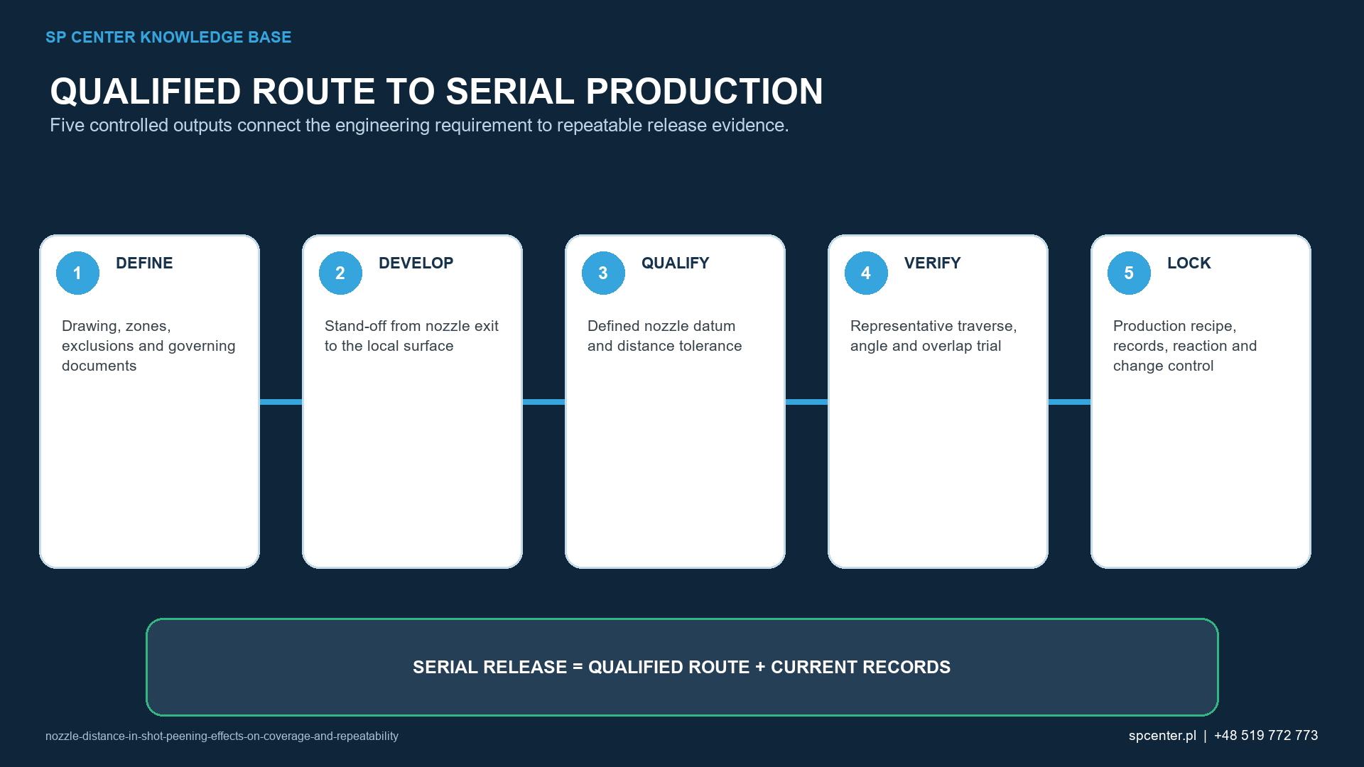
Which failures require containment?
- Distance or angle exceeds the approved range at any required location.
- Nozzle TCP, fixture datum or component seating cannot be verified.
- Nozzle wear, damage or replacement changes the qualified physical datum.
- Path revision changes overlap, boundaries or motion without impact review.
- Intensity or coverage evidence is missing for the affected configuration.
- Extra exposure was used to compensate for a geometric error without authority.
Contain all potentially affected product to the last known acceptable condition. Reprocessing needs explicit review because cumulative exposure can change roughness, dimensions, cold work and residual stress.
Frequently asked questions
What is nozzle stand-off distance in shot peening?
It is the controlled separation between a defined nozzle datum and the local component surface, measured in the direction specified by the qualified setup.
Does moving the nozzle closer always increase intensity?
No. Nozzle design, acceleration, airflow, media, angle and measurement location interact. Establish intensity through the applicable Almen and saturation procedure for the complete configuration.
Does a longer distance improve coverage?
It may broaden the footprint but can also reduce usable particle energy and definition. Coverage rate and final coverage must be qualified on representative geometry.
Should distance be measured normal to the surface?
Only when the approved definition says so. A setup may define distance along the nozzle axis, to a local normal construction or through another controlled datum; ambiguity must be removed.
How is stand-off controlled on a curved component?
Map distance and angle along the path, use verified part and fixture datums, and challenge the most sensitive locations with representative intensity and coverage evidence.
Does a robot programme prove the distance?
No. Tool-centre-point calibration, nozzle condition, fixture location, component seating and programme version must also be controlled and verified.
When does a nozzle change require review?
Review a change in nozzle type, bore, length, material, holder, wear state or tool datum because it can alter stream velocity, origin, footprint and qualified equivalence.
What should an RFQ specify?
Provide part geometry, treatment and exclusion zones, intensity and coverage requirements, equipment constraints, known nozzle-distance definition, tolerances, quantity and required qualification and batch records.
Key takeaways
- Stand-off needs a physical datum, measurement direction and tolerance.
- Closer is not universally better, and farther does not automatically improve coverage.
- Distance interacts with nozzle, airflow, media mass flow, angle, traverse and overlap.
- Robot coordinates do not by themselves prove the physical nozzle-to-part relationship.
- Intensity, coverage, path repeatability and component acceptance require separate evidence.
- Nozzle wear, fixture movement and part seating belong in the control plan.
Related SP Center guides
- Air Pressure and Flow in Pneumatic Shot Peening
- Impact Angle in Shot Peening
- Exposure Time in Shot Peening
Technical references
1. SAE J2441_202511: Shot Peening, stabilized November 2025
2. SAE AMS2430U: Shot Peening, revised April 2018
3. SAE ARP7488: Peening Design and Process Control Guidelines, issued January 2018
4. SAE J443_202512: Procedures for Determining and Verifying Peening Intensity, revised December 2025
5. SAE J2277_202301: Shot Peening Coverage Determination, revised January 2023
Standards note: Use the complete requirements invoked by the drawing, contract and customer. No universal stand-off range applies to every nozzle, medium or component.
Author: Paweł Kmieć
Discuss a pneumatic shot peening requirement: +48 519 772 773 | [email protected]