


How acceleration method, geometry, productivity and process evidence affect equipment selection
Air-blast and wheel-blast shot peening accelerate media by different mechanisms. Air systems typically provide flexible stream direction and specialised access; centrifugal wheels can provide high media throughput and efficient serial processing. Neither architecture is inherently superior. Selection depends on component access, media, production strategy and the ability to qualify and reproduce the required component-level process.
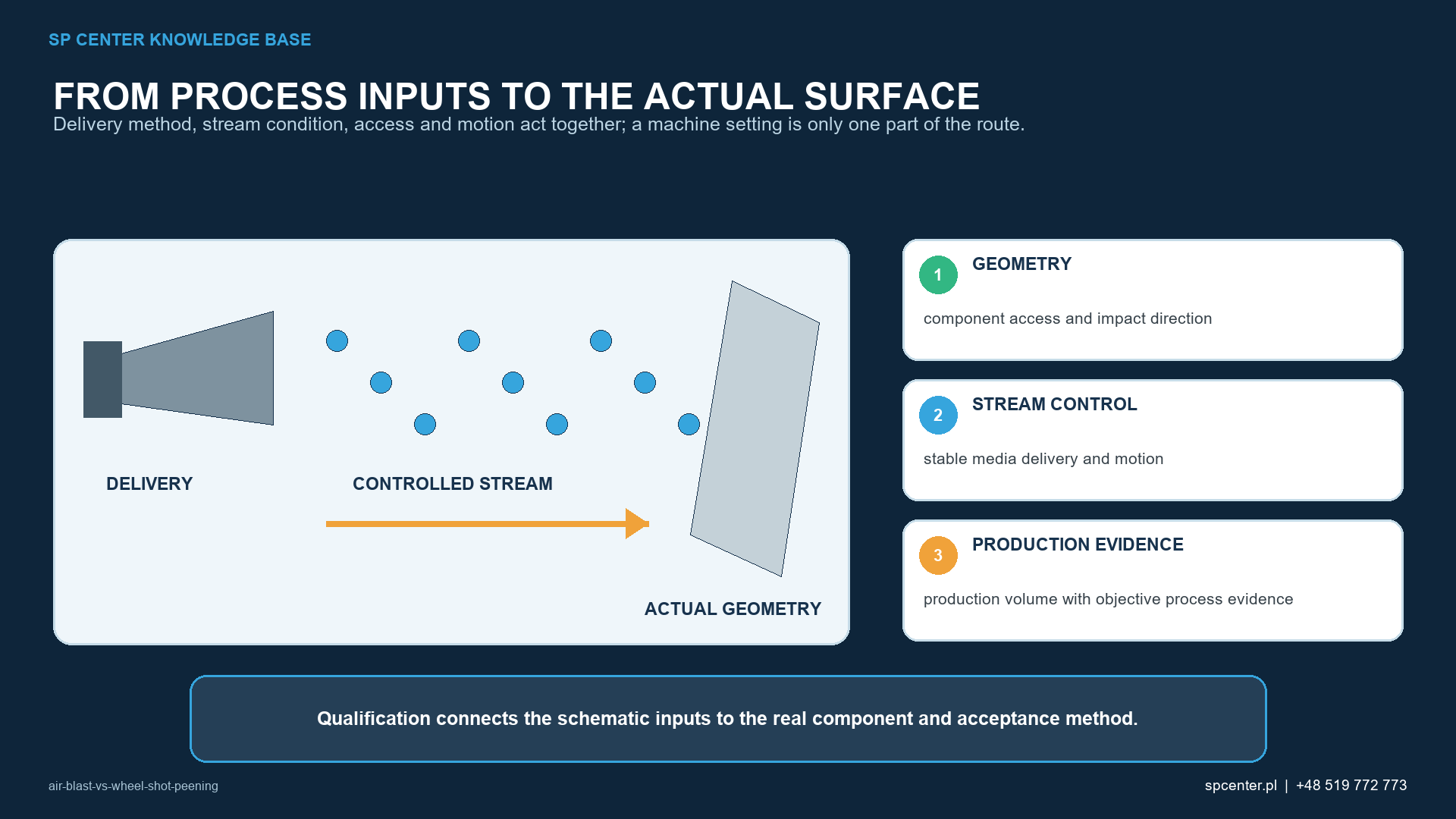
Figure 1 is a technical decision aid for air-blast vs wheel shot peening. It does not contain a universal recipe or replace the governing drawing, specification, qualification and component acceptance evidence.
Why does the acceleration method alone not determine process quality?
Two machines can meet the same Almen intensity and coverage requirement without being operationally interchangeable. Intensity characterizes the standardized response of the peening stream at defined verification locations; coverage evaluates specified component surfaces. Neither result alone proves identical particle-velocity distribution, impact-angle distribution, exposure uniformity, surface condition or long-term stability.
| Evidence | What it supports | What it does not prove alone |
|---|---|---|
| Almen intensity | Response of the stream at the verified location and setup. | Coverage or identical delivery across the component. |
| Coverage | Specified surface meets the invoked impact-evidence criterion. | Correct intensity, surface integrity or fatigue performance. |
| Machine records | Selected inputs and monitored states stayed within authorised limits. | That unmonitored variables remained stable. |
| Component inspection | Specified acceptance characteristics are conforming. | An unspecified residual-stress profile or life improvement. |
Table 1. Equipment capability is demonstrated through complementary evidence.
How does air-blast shot peening control the media stream?
An air-blast system accelerates media through a nozzle using compressed air. It can provide flexible aiming and independent control of multiple nozzles, which is valuable for complex geometry, development work and low-to-medium production volumes. Suitability depends on the complete delivery arrangement, not on the word “air” in the machine description.
| Controlled element | Why it matters | Typical degradation or variation |
|---|---|---|
| Air supply and pressure | Influence available energy and repeatability of the nozzle stream. | Supply fluctuation, restriction, leakage or regulator drift. |
| Media flow | Affects particle flux and coverage rate. | Feeder instability, bridging, blockage or sensor error. |
| Nozzle condition | Affects stream shape, direction and efficiency. | Bore wear, damage, misalignment or replacement mismatch. |
| Stand-off and angle | Control access, footprint and impact direction. | Fixture shift, robot error or incorrect setup. |
| Motion and exposure | Distribute the stream over the treatment area. | Recipe, speed, path or timing deviation. |
Table 2. Air-blast stability depends on the complete pneumatic and positioning system.
How does wheel-blast shot peening control the media stream?
A centrifugal wheel accelerates media mechanically with rotating blades. Wheel systems can deliver high media throughput and are often attractive for repeatable serial production. Their applicability is determined by the required stream access, impact direction, process window and component-handling strategy – not simply by production volume.
- Wheel speed: Why it matters: Influences media exit velocity and the resulting stream.; Typical degradation or variation: Drive variation, control error or unauthorised setting change.
- Media flow: Why it matters: Influences particle flux and loading of the wheel.; Typical degradation or variation: Flow-control wear, blockage or inconsistent feed.
- Blades and wheel parts: Why it matters: Define acceleration and discharge behaviour.; Typical degradation or variation: Wear, imbalance, damage or inconsistent replacement parts.
- Control cage / discharge setting: Why it matters: Influences the position of the blast pattern.; Typical degradation or variation: Wear, incorrect adjustment or assembly error.
- Part motion and presentation: Why it matters: Determine which surfaces receive the stream.; Typical degradation or variation: Fixture wear, orientation error or cycle variation.
Table 3. Wheel-blast control includes both the wheel and the component-delivery system.
How do air-blast and wheel-blast systems compare for engineering selection?
| Selection question | Air-blast tendency | Wheel-blast tendency |
|---|---|---|
| Geometry and access | Flexible nozzle placement can support local or complex access. | Best where a stable wheel pattern can reach all required areas. |
| Production strategy | Well suited to development, variants and flexible cells. | Often efficient for repeatable, higher-throughput routes. |
| Motion architecture | Nozzle and/or component motion may be programmed independently. | Component presentation is coordinated with the fixed wheel pattern. |
| Primary wear focus | Nozzles, hoses, valves, feeders and air system. | Blades, control cage, liners, wheel parts and feed system. |
| Qualification consequence | Qualify the actual nozzles, positions, paths and pneumatic settings. | Qualify the actual wheel, discharge pattern, settings and part motion. |
Table 4. These are selection tendencies, not universal capability limits.
KEY DECISION Select the architecture that can deliver and control the required process on the real component. A technology label is not a substitute for access trials, stream qualification, coverage development and component acceptance.
Why is process stability a property of the complete system?
Stable production requires equipment, media, tooling, software, maintenance and verification to work as one controlled system. Replacing a machine, nozzle, wheel component, fixture or motion program can change delivery even when the nominal settings appear unchanged.
- Define the approved equipment identity and configuration.
- Control media type, size distribution, condition and replenishment.
- Control fixtures, masking, part orientation, nozzle/wheel position and motion.
- Identify monitored variables, recording frequency, alarm limits and reaction plans.
- Evaluate changes through the applicable change-control and requalification route.
What can automation and computer monitoring establish?
Automation improves repeatability when it consistently executes an already qualified process. Programmable recipes, interlocks, monitored media flow, position confirmation and production records can reduce uncontrolled variation and strengthen traceability. They do not demonstrate that the selected path reaches the critical surface or that the engineering process is suitable.
| Control layer | Useful evidence | Required caution |
|---|---|---|
| Recipe management | Authorised setpoints and cycle selection. | Protect versions and prevent unauthorised edits. |
| Real-time monitoring | Recorded states for specified process variables. | A recorded signal is useful only if the sensor and limit are valid. |
| Interlocks and alarms | Prevention or detection of defined abnormal states. | A bypass or weak reaction plan can defeat the control. |
| Motion control | Repeatable position, path, speed and timing. | Tool centre point, fixture datum and payload changes can affect delivery. |
| Data retention | Traceability to part, lot, recipe and equipment. | Records should support – not replace – physical verification. |
Table 5. Monitoring must be tied to validated variables, limits and reactions.
Why is maintenance part of process control?
Wear does not always cause an immediate machine stop. It can gradually change stream shape, discharge location, media flow or motion accuracy while production continues. Preventive maintenance therefore protects process stability as well as equipment availability.
- Define inspection and replacement criteria for wear parts.
- Use verified replacement parts and restore approved adjustments after maintenance.
- Check the separator, screens, recovery system and media feed – not only the accelerator.
- Assess leaks, sensor drift, robot or fixture accuracy and abnormal vibration.
- Define post-maintenance verification and escalation according to the risk of the intervention.
Maintenance verification: A maintenance record confirms that work occurred. It does not by itself confirm restoration of the qualified stream. The required verification depends on what changed and on the governing process documentation.
How should each machine configuration be qualified and verified in production?
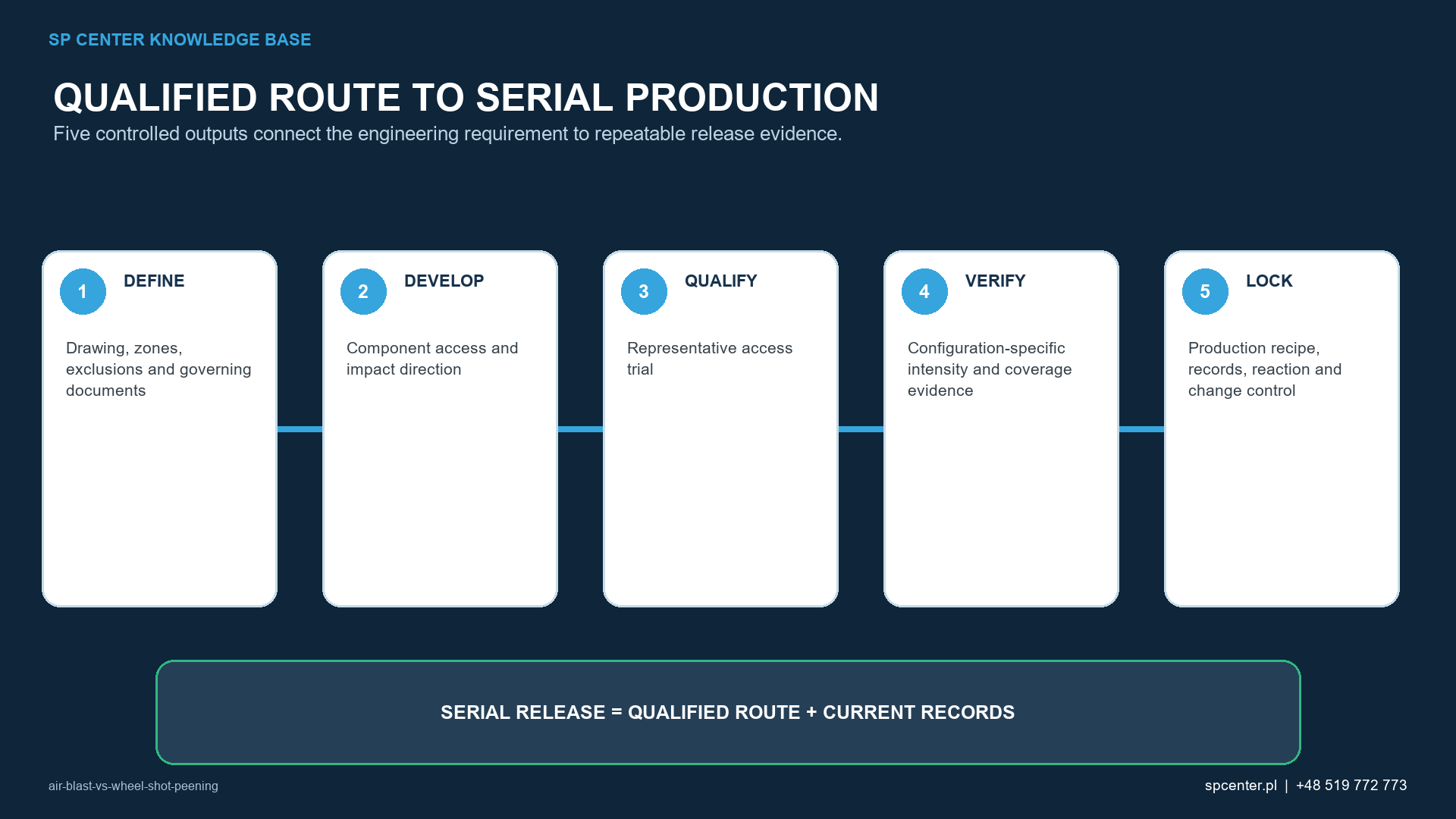
- 1. Requirement review: Required output: Treatment area, intensity, coverage, media, exclusions and controlling documents.
- 2. Equipment selection: Required output: Architecture and capacity suitable for access, motion and production strategy.
- 3. Delivery development: Required output: Nozzle/wheel configuration, fixture, masking, part presentation and exposure.
- 4. Stream qualification: Required output: Saturation curve, Almen intensity and defined verification locations.
- 5. Component evaluation: Required output: Coverage, boundaries, surface condition and other invoked acceptance checks.
- 6. Control plan: Required output: Monitored variables, limits, records, maintenance and reaction plan.
- 7. Serial verification: Required output: Evidence that the authorised process continues to be reproduced.
Table 6. Qualification connects equipment settings to component-level evidence.
Which questions matter when evaluating equipment?
- Can the stream reach every specified surface at an appropriate impact direction?
- Which variables are controlled, monitored, recorded and interlocked?
- How are media flow, recovery, separation and replenishment managed?
- Which wear components can shift stream performance, and how are limits established?
- How are fixtures, masking, part identification and recipes controlled?
- What verification is required after maintenance, setup change or software revision?
- Can the system reproduce the qualified cycle with objective evidence over time?
How should air-blast and wheel-blast shot peening be specified and qualified?
Qualification must connect the actual component to a controlled production route. For air-blast and wheel-blast shot peening, the technical review should address component access and impact direction, stable media delivery and motion, production volume with objective process evidence. A successful trial is not transferable when the equipment, media, tooling, geometry, motion, preparation or acceptance method changes without review.
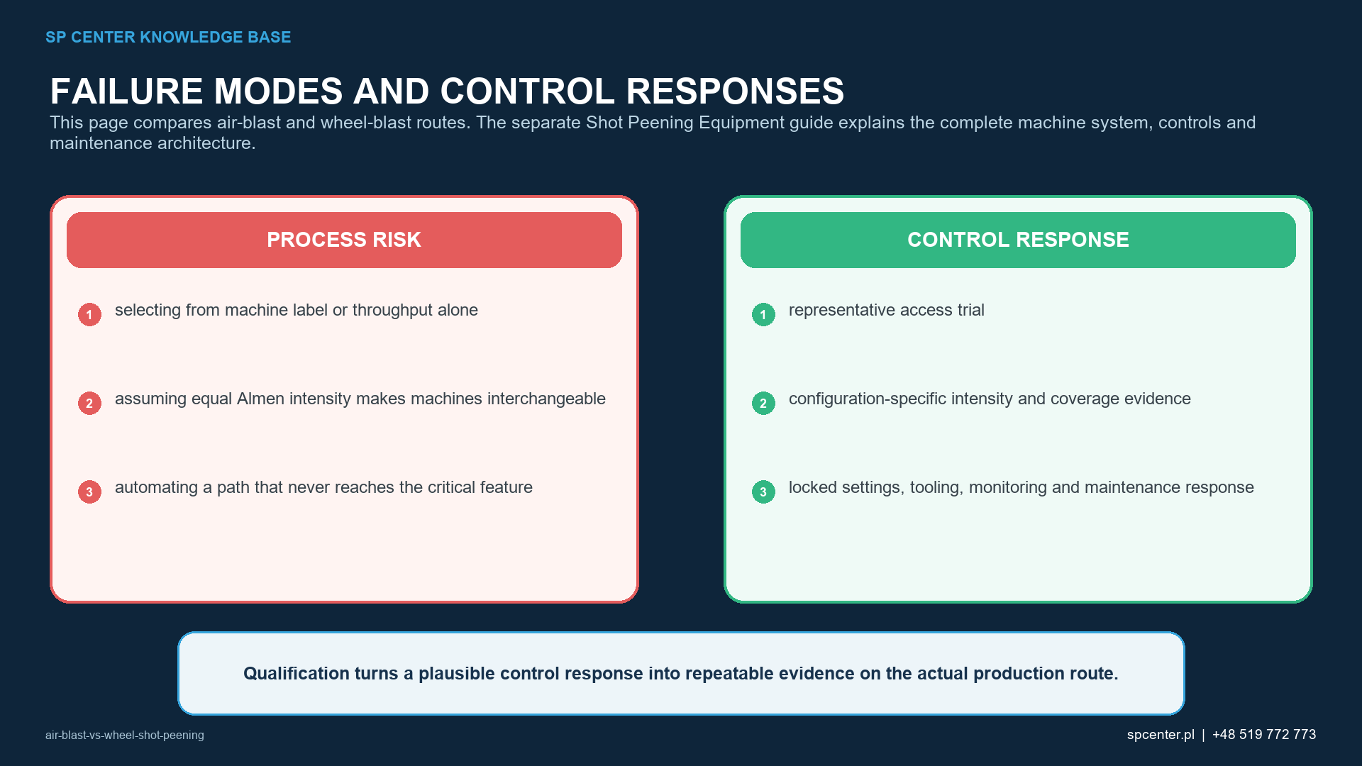
The release plan should address the process-specific risks: selecting from machine label or throughput alone, assuming equal Almen intensity makes machines interchangeable, automating a path that never reaches the critical feature. SP Center can propose feasibility work and a process-control route, but the drawing, invoked specifications, approved deviations and customer flow-down remain the contractual authority.
| RFQ input | Why it matters |
|---|---|
| Controlled drawing and revision | Defines the part identity, treatment zones, boundaries and exclusions. |
| Material, heat treatment and incoming surface | Supports media, damage, roughness, contamination and sequence review. |
| Governing specifications and customer flow-down | Identifies the authority for intensity, coverage, media, records and acceptance. |
| Geometry, size, mass and representative features | Supports feasibility for component access and impact direction and the worst-access location. |
| Quantities, lot logic and delivery plan | Allows a production route, capacity plan, traceability level and commercial basis to be defined. |
| Surface, dimensional and record requirements | Prevents intensity or coverage from being treated as the only release evidence. |
Table 5. RFQ inputs for a controlled project review.
RFQ SUPPORT Send the controlled drawing, requirements and quantity to [email protected]. For an initial feasibility discussion, call +48 519 772 773.
Which misconceptions about air-blast and wheel-blast shot peening should be avoided?
The assumption “The newest machine produces the best process.” is incorrect. capability depends on qualified delivery and sustained control.
The assumption “Air blast is always more accurate.” is incorrect. accuracy and repeatability depend on the actual system and application.
The assumption “Wheel blast is only for simple parts.” is incorrect. suitability depends on access, pattern, motion and requirements.
The assumption “Automation guarantees quality.” is incorrect. it reproduces instructions and monitors selected variables, whether or not the process was correctly developed.
The assumption “Matching Almen intensity makes two machines equivalent.” is incorrect. component delivery and acceptance evidence remain configuration-specific.
Frequently asked questions about air-blast and wheel-blast shot peening
What is Air-Blast vs Wheel Shot Peening?
Air-blast and wheel-blast shot peening accelerate media by different mechanisms. Air systems typically provide flexible stream direction and specialised access; centrifugal wheels can provide high media throughput and efficient serial processing.
Is air-blast shot peening more accurate than wheel shot peening?
Air-blast shot peening is not automatically more accurate. Accuracy and repeatability depend on the complete nozzle or wheel system, component presentation, motion, media control, maintenance and qualification evidence.
Can an air-blast and wheel-blast machine use the same qualified recipe?
A recipe should not be transferred on nominal settings alone. The new production configuration must demonstrate the required intensity, access, coverage, surface condition and serial repeatability under the governing approval route.
Which variables control air-blast vs wheel shot peening?
Air-Blast vs Wheel Shot Peening depends on component access and impact direction, stable media delivery and motion, production volume with objective process evidence. The production route must also control representative access trial, configuration-specific intensity and coverage evidence, locked settings, tooling, monitoring and maintenance response.
Does correct Almen intensity prove air-blast vs wheel shot peening is acceptable?
Correct Almen intensity proves only the standardized stream response required by the invoked procedure. Air-blast and wheel-blast routes require configuration-specific evidence. The separate Shot Peening Equipment guide explains the complete machine system, controls and maintenance architecture.
What should an RFQ for air-blast vs wheel shot peening include?
Send the controlled drawing and revision, material and heat treatment, required treatment and exclusion zones, governing specifications, intensity and coverage requirements, quantities, surface and dimensional limits, and required records.
Which standards apply to air-blast vs wheel shot peening?
The applicable documents depend on the contract and component. Relevant technical references include SAE J2441_202511, SAE J443_202512, SAE J442_202602, AMS2430U, but the revisions invoked by the drawing and customer flow-down remain authoritative.
Can SP Center assess an air-blast vs wheel shot peening requirement?
Yes. SP Center can review feasibility, process controls, trials, qualification evidence and serial requirements within its confirmed capability and approval scope. Call +48 519 772 773 or send the controlled documentation to [email protected].
What are the key takeaways?
- Machine architecture determines how media is accelerated and delivered.
- Choose between air blast and wheel blast from component access, production strategy and controllability.
- Treat equipment, media, tooling, software, maintenance and verification as one process system.
- Qualify the production configuration actually used and control material changes.
- Use automation and monitoring to support – not replace – engineering qualification and component evidence.
Which related SP Center guides should be read next?
Which technical references support this guide?
1. SAE J2441_202511: Shot Peening, stabilized November 2025
2. SAE J443_202512: Procedures for Determining and Verifying Peening Intensity, revised December 2025
3. SAE J442_202602: Tools for Peening Intensity Determination and Verification, revised February 2026
4. SAE AMS2430U: Shot Peening, revised April 2018
5. SAE AMS2432E: Shot Peening, Computer Monitored, revised October 2022
6. SAE AMS2431E: Peening Media, General Requirements, revised April 2023
7. SAE J2277_202301: Shot Peening Coverage Determination, revised January 2023
Applicable revisions: Use the complete revisions invoked by the drawing, contract and customer flow-down. This article provides engineering context and does not replace controlled requirements.
Author: Paweł Kmieć
Discuss this shot peening requirement: +48 519 772 773 | [email protected] | shot peening service