


Control robot motion, coordinate systems, tooling, shot-stream inputs, recovery logic and component evidence as one qualified production system
Robotic shot peening can reproduce complex nozzle or component motion with high consistency, but automation is not proof of a conforming process. A capable route connects the robot base, tool centre point (TCP), fixture and component datum to a qualified shot stream, verified path, controlled recipe, component coverage and traceable release.
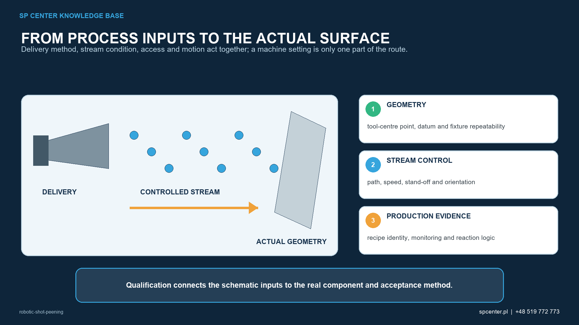
What does the robot control—and what remains separate?
| Control layer | What it establishes | What it does not establish by itself |
|---|---|---|
| Robot and positioner motion | Repeatable commanded position, orientation, sequence and relative movement | Correct particle trajectory, stable media delivery or conforming component result |
| Coordinate systems and TCP | Relationship among robot base, tool, fixture and component datum | That the loaded component or replacement tool is actually in the qualified location |
| Shot-stream controls | Authorised settings for air pressure or wheel speed, media mass flow, tool identity and related inputs | Complete component coverage or acceptable surface integrity |
| Almen intensity | Standardised response of the verified stream and setup | Local access, impact geometry, coverage or residual-stress profile on the component |
| Component inspection | Coverage, boundaries, surface condition and other invoked acceptance evidence | Long-term fatigue performance without the required engineering validation |
Table 1. Robot repeatability, process capability and component acceptance are related but different evidence layers.
Repeatability means that the system can reproduce the same commanded motion. Accuracy asks whether that motion corresponds to the intended physical geometry. Process capability additionally requires stable media acceleration and delivery, a controlled component condition and evidence that the specified result is achieved.
How are coordinate systems and tooling controlled?
The production route must define the relationship among the robot base, tool frame/TCP, positioner, fixture, component datum and feature-local surface. A correct program can run in the wrong physical location when a part is mis-seated, a locator contains debris, the fixture is worn, a replacement nozzle has a different length or the TCP has not been reverified.
Tool identity and dimensions, installation, payload, mastering, fixture identity, seating and clamp state therefore belong to the controlled setup. Where risk justifies it, position or presence checks should prevent cycle start with an incorrect part, fixture, tool or orientation.
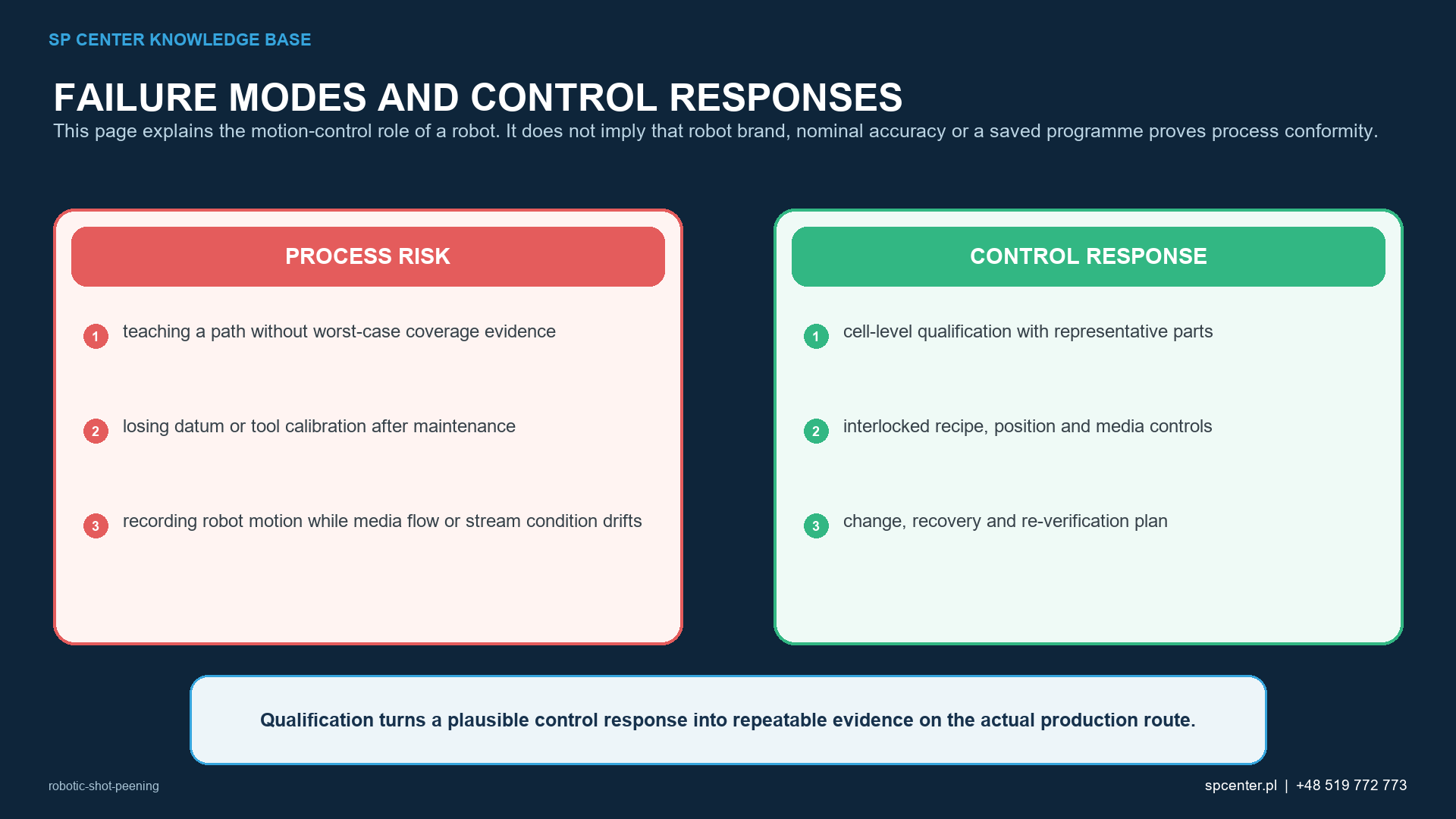
Why does the executed path matter more than nominal coordinates?
| Path or geometry event | Potential failure mode | Required control |
|---|---|---|
| Lead-in, lead-out or direction reversal | Local dwell, untreated entry band or repeated exposure | Place transients outside the treatment zone where possible and verify the real executed path |
| Corner, wrist reorientation or path blending | Actual TCP speed and impact angle differ from the nominal segment | Validate controller dynamics with the production payload, tool and coordinated axes |
| Adjacent passes | Gap or excessive overlap in the effective stream footprint | Qualify pass spacing, sequence, orientation and overlap against component evidence |
| Rotation or indexed positioner | Phase, backlash, missed index or synchronisation error | Control home, index identity, coordinated motion, mechanical condition and fault reaction |
| Narrow recess or internal feature | Shadowing, rebound, tool collision or media entrapment | Qualify the specific lance/nozzle, access route, coverage method and media-removal plan |
| Interrupted cycle and restart | Missed area or double-treated area | Use an authorised recovery state and defined restart boundary; retain event records |
Table 2. Dynamic path events and recovery states can change local exposure even when the saved point list is unchanged.
Robot reach, singularities, joint limits, cable and hose routing, payload, axis acceleration and controller path blending can alter the feasible or executed motion. Qualification must observe the production configuration rather than rely only on offline programming, a digital twin or nominal robot accuracy.
Which process variables must be monitored with robot motion?
Depending on the qualified equipment, relevant inputs can include media identity and condition, media mass flow, air pressure and air-flow conditions, nozzle/lance identity, or wheel speed and feed controls. Stand-off, orientation, traverse, part rotation, exposure sequence and alarms must be connected to the authorised recipe and reaction plan.
A completed cycle without a detected alarm proves only that the monitored conditions and logic reported completion. It does not independently prove that an unmonitored nozzle has not worn, the part was correctly seated, every required surface received the stream or the component has the intended residual-stress profile.
How are programs, recipes and changes governed?
| Configuration item | Production control | Review or requalification trigger |
|---|---|---|
| Program and recipe | Released identifier, revision, access rights, backup and audit trail | Path, speed, sequence, process limit, logic or controller-software change |
| Nozzle, lance and TCP | Tool identity, dimensions, wear limit, installation and TCP verification | Replacement, repair, collision, wrist work or changed payload |
| Fixture and component datum | Fixture identity, seating, cleanliness, clamping and locator condition | Wear, repair, relocation, new part variant or datum change |
| Robot and positioner | Mastering, home checks, maintenance status and accuracy appropriate to risk | Axis repair, mastering loss, crash, calibration failure or moved equipment |
| Media-delivery system | Media identity/condition, mass flow and applicable pressure, velocity or wheel controls | Feeder, hose, nozzle, wheel, sensor, separator or media-system change |
| Inspection and records | Almen route, component coverage, surface acceptance, alarms and serial/lot traceability | Changed acceptance method, critical location, customer requirement or unexplained trend |
Table 3. Configuration control must cover software, tooling, geometry and the physical stream.
Released program and recipe identifiers should be linked to the component and revision. Authorised access, backup, restore testing, audit trail and change approval prevent an edited or recovered file from silently becoming the production master. A checksum can support identity, but it does not prove the engineering suitability of the program.
How should cycle interruption and manual touch-up be handled?
Power loss, media-flow fault, axis alarm, emergency stop or loading error can interrupt treatment mid-zone. The recovery plan must identify a safe state and a restart boundary that prevents an untreated gap or uncontrolled repeat exposure. The event, affected serial or lot identity, recovery route and disposition should remain traceable.
Manual touch-up is not an automatic recovery method. It may be used only when the governing requirements and approved process route authorise a qualified manual operation with defined parameters, access, verification and records.
How is a robotic shot peening process qualified?
| Qualification stage | Minimum engineering output | Typical evidence |
|---|---|---|
| Requirements review | Treatment and exclusion zones, governing documents, media, intensity, coverage and acceptance authority | Controlled drawing, specification matrix and resolved technical questions |
| Cell definition | Robot, positioner, fixture, tool, stream system, sensors, software and coordinate frames | Configuration list, calibration/mastering status and controlled layout |
| Path development | TCP, stand-off, orientation, speed, overlap, sequence, start/stop and restart logic | Released program/recipe and verified real-path observations |
| Stream verification | Applicable saturation-curve route and intensity verification locations | Almen records under the invoked procedure |
| Component qualification | Worst-access coverage, boundaries, surface condition and other required validation | Representative-part or authorised surrogate evidence and approved results |
| Production control | Interlocks, monitoring, reaction plan, access, traceability, maintenance and change control | Cycle/exception records, inspection results and authorised release |
Table 4. Qualification translates a digital motion program into controlled physical evidence at the component.
Worst-access prescribed locations deserve explicit coverage evidence. Almen intensity and the saturation curve address standardised stream response under the invoked procedure; they do not replace component coverage or acceptance of boundaries, roughness, dimensions, cleanliness and other specified surface conditions.
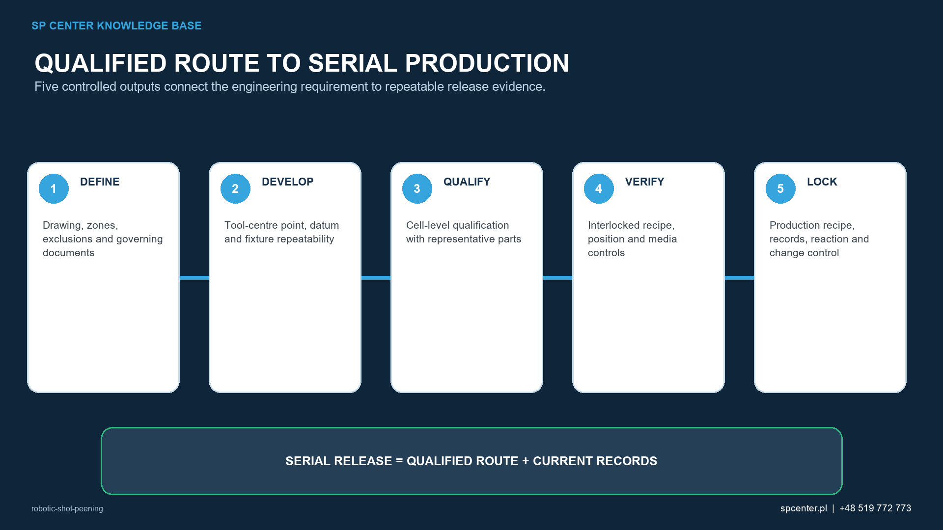
What must maintenance and fault response protect?
Preventive maintenance should cover robot and positioner mechanics, mastering, hoses and cables, tooling, fixture locators, media delivery, sensors and safety-related interlocks. The control plan must define which events require a setup check, intensity verification, coverage check, representative-part trial or broader requalification. The decision depends on the possible effect of the change, not only on whether the machine can move again.
What is robotic shot peening?
It is shot peening in which a robot controls part or tool motion within a qualified cell. The robot reproduces an authorised path; media generation, tooling, fixture, inspection and records remain separate parts of process control.
Does a robot guarantee repeatable shot peening?
No. It can repeat commanded motion, but the result also depends on coordinate accuracy, TCP, fixture and part location, nozzle condition, media mass flow, pressure or wheel variables, media condition and component verification.
Which robot variables affect local exposure?
Path, actual TCP speed, orientation, stand-off, overlap, pass count, sequence, acceleration and deceleration, positioner coordination and restart logic can all affect the exposure delivered to a local surface.
Does correct Almen intensity prove the robotic path is acceptable?
No. Almen intensity verifies a standardised stream response for the defined setup. Component access, local impact geometry, complete coverage, boundaries and surface condition require separate evidence.
Can offline programming or a digital twin qualify the process?
No. Simulation is useful for reach, collision and path development, but it does not by itself validate the real tool, fixture, stream, component coverage, surface response or fault behaviour.
What should happen after a robot collision or tool change?
The approved reaction plan should assess mastering, TCP, tool identity, fixture, path and stream configuration, then require the defined verification or requalification before production resumes.
Can an interrupted robotic cycle simply be restarted?
Only through the authorised recovery logic. The restart point must prevent both missed and double-treated areas, and the event and disposition must remain traceable.
Does AMS2432E apply to every robotic shot peening process?
Not automatically. It applies when invoked by the drawing, contract or customer flow-down. A robotic cell may be computer-monitored, but applicability and the required evidence must be established from the governing documents.
Key takeaways
- A robot repeats motion; it does not independently qualify the shot stream or accept the component.
- Control robot base, TCP, tool, fixture, component datum and positioner as one geometry chain.
- Qualify actual path dynamics, overlap, start/stop states and coordinated motion.
- Monitor physical stream inputs as well as digital program execution.
- Protect recipe versions, access, backups, recovery and change approval.
- Verify Almen intensity and component coverage as separate evidence.
- Define restart and post-maintenance verification before a fault occurs.
Related SP Center guides
Technical sources
1. SAE AMS2432E: Shot Peening, Computer Monitored, revised October 2022
2. SAE AMS2430U: Shot Peening, revised April 2018
3. SAE ARP7488: Peening Design and Process Control Guidelines, issued January 2018
4. SAE J443_202512: Procedures for Determining and Verifying Peening Intensity, revised December 2025
5. SAE J2277_202301: Shot Peening Coverage Determination, revised January 2023
6. SAE J2441_202511: Shot Peening, stabilized November 2025
Standards note: Applicability and revision are controlled by the drawing, contract and customer flow-down. AMS2432E is not cited here as a universal requirement for every robotic cell, and this guide does not replace the complete invoked documents.
Author: Paweł Kmieć
Discuss robotic shot peening feasibility and qualification: +48 519 772 773 | [email protected]