


How air pressure, air delivery, media mass flow, nozzle condition and monitoring become one qualified shot stream
Air pressure and flow in pneumatic shot peening are related process inputs, but they are not interchangeable and neither one is Almen intensity. Pressure describes the gas state at a defined location and operating condition; air flow describes the gas delivered through the system; media mass flow describes the shot delivered per unit time. Together with the media, feeder, hose, nozzle or lance, distance, angle and motion, these inputs influence particle velocity, particle flux and the delivered footprint. A defensible production process therefore controls the complete pneumatic configuration and confirms its output with the specified Almen intensity, coverage, component inspection and traceable reaction plan.
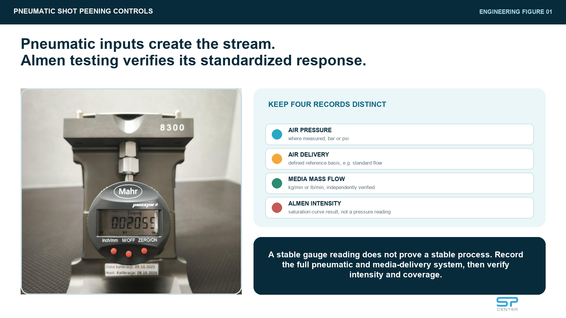
Figure 1. Pneumatic inputs create the stream; Almen testing verifies its standardized response.
Figure 1 uses a real SP Center Almen gage. It separates standardized intensity verification from three pneumatic inputs that must be defined and recorded independently: pressure, air delivery and media mass flow.
What do air pressure and flow control in pneumatic shot peening?
In pneumatic shot peening, compressed air transfers energy to peening media as the two-phase stream moves through the mixing system, hose and nozzle. Air pressure, gas delivery and media loading influence the acceleration available to the particles. The nozzle or lance then shapes the stream, while distance, angle and motion determine where that stream meets the component. The machine inputs therefore act as a connected system, not as isolated numbers on a screen.
Air pressure does not equal particle velocity. The relationship depends on the machine, nozzle geometry, media diameter and density, shot mass rate, hose losses and measurement location. Published experiments confirm that pressure can have a strong effect within one fixed setup, but the fitted relationship changes with the equipment. A setting from one machine should not be used as a conversion formula for another machine.
Air pressure and flow also do not replace product evidence. SAE AMS2432E describes computer-monitored shot peening as real-time observation, traceability and response for process input settings, with AMS2430 forming an integral part of the specification. That monitoring supports control of the route. The required Almen intensity, coverage and component acceptance still close different engineering questions.
Process-control principle: Control the pneumatic system as one qualified configuration. Never approve a process from regulator pressure or feeder command alone.
Which quantities must remain separate in a pneumatic shot peening record?
A useful record separates air pressure, air flow, media mass flow, particle velocity, particle flux and Almen intensity because each quantity has a different physical meaning. Pressure is force per area. Air flow is a gas quantity per time. Media flow is solid mass per time. Particle velocity and flux describe the resulting stream. Almen intensity is a standardized response derived by the prescribed test method.
Units alone do not make values comparable. One bar equals 100 kPa, and one psi equals approximately 6.894757 kPa, but a correct conversion does not resolve gauge versus absolute pressure or the point of measurement. Gas-flow values also need reference temperature and pressure. NIST warns that terms such as standard cubic centimetres per minute can use different temperature conventions. The reference basis must travel with the number.
The record should state whether a value is a setpoint, command, indicated value, independently measured value, calculated value or alarm limit. A feeder percentage is not a mass-flow result unless the released system establishes and maintains that relationship. A regulator setpoint is not nozzle pressure unless the measurement basis and dynamic losses make that statement valid for the actual configuration.
| Quantity | Engineering meaning | Minimum definition for a controlled record |
|---|---|---|
| Air pressure | Static or dynamic pressure at a named point in the pneumatic circuit | Measurement point, gauge or absolute basis, operating state, units, sensor and time basis |
| Air flow or capacity | Gas mass flow or volumetric delivery expressed at stated conditions | Measurement method, reference temperature and pressure, humidity basis if relevant, range and units |
| Media mass flow | Mass of peening media delivered per unit time | Measured or verified value, time interval, media condition, calibration or gravimetric method and stability |
| Particle velocity | Distribution of particle speeds at a defined position in the stream | Measurement location, media, nozzle, pressure, mass loading, distance and diagnostic method |
| Particle flux | Particle population crossing an area per unit time | Area, time basis, stream position, media distribution and method |
| Almen intensity | Standardized mechanical response derived using the prescribed Almen system | Strip type, holder location, exposure sequence, curve or verification method and result |
Table 1. Pressure, air delivery, media mass flow and Almen intensity are related but not interchangeable quantities.
Why is regulator pressure not the same as pressure at the nozzle?
Pressure changes through a working pneumatic system because flow through filters, valves, fittings, hoses, mixers, lances and nozzles creates losses. A plant header can remain stable while the machine inlet or downstream circuit droops under demand. A regulator can also show a different value at no-flow, start-up and steady peening conditions. Every pressure value therefore needs a location and an operating state.
Gauge pressure and absolute pressure are different bases. Gauge pressure is referenced to local atmospheric pressure; absolute pressure is referenced to vacuum. Most shop displays use gauge pressure, but calculations and technical papers may use absolute pressure or explicitly add atmospheric pressure. Mixing the two produces a numerical error even when the units are converted correctly.
The most useful sensor location is the one that answers the control question without creating an unreliable installation. A sensor closer to the delivery circuit may represent the process more directly, but it still has response, calibration, contamination, vibration and maintenance limits. The process plan should distinguish the primary control point from diagnostic points upstream or downstream.
Measurement principle: Record plant header, machine inlet, regulator outlet and delivery-circuit values as different measurements. Do not rename one as another.
How do air pressure and media mass flow interact?
At a fixed displayed pressure, increasing media mass loading means the gas must accelerate more solid material through the same delivery system. Depending on the feeder and nozzle, the change can alter particle-velocity distribution, stream concentration, pressure loss and footprint. At a fixed media-flow reading, a change in nozzle geometry, air capacity or hose condition can still produce a different stream.
A published pneumatic shot peening experiment illustrates why a result must stay tied to its setup. Ohta, Tsutsumi and Ma measured ASR170 steel shot at about 30 m/s with 0.14 MPa air pressure and about 49 m/s with 0.35 MPa in their specific direct-pressure machine; the measured steady velocity followed approximately the 0.51 power of pressure for that configuration. Those figures are evidence of interaction, not production setpoints for another machine, medium or component.
The practical development method is to vary pressure and media mass flow deliberately while holding the documented nozzle, hose, media, distance and witness setup constant. Record both average values and stability, then establish Almen intensity and component delivery independently. The released operating window should exclude combinations that meet one displayed input but create unstable delivery, poor coverage, surface damage or unacceptable productivity.
Qualification limit: Pressure-to-velocity and pressure-to-intensity relationships belong to the tested configuration. Copying a curve between machines is not qualification.
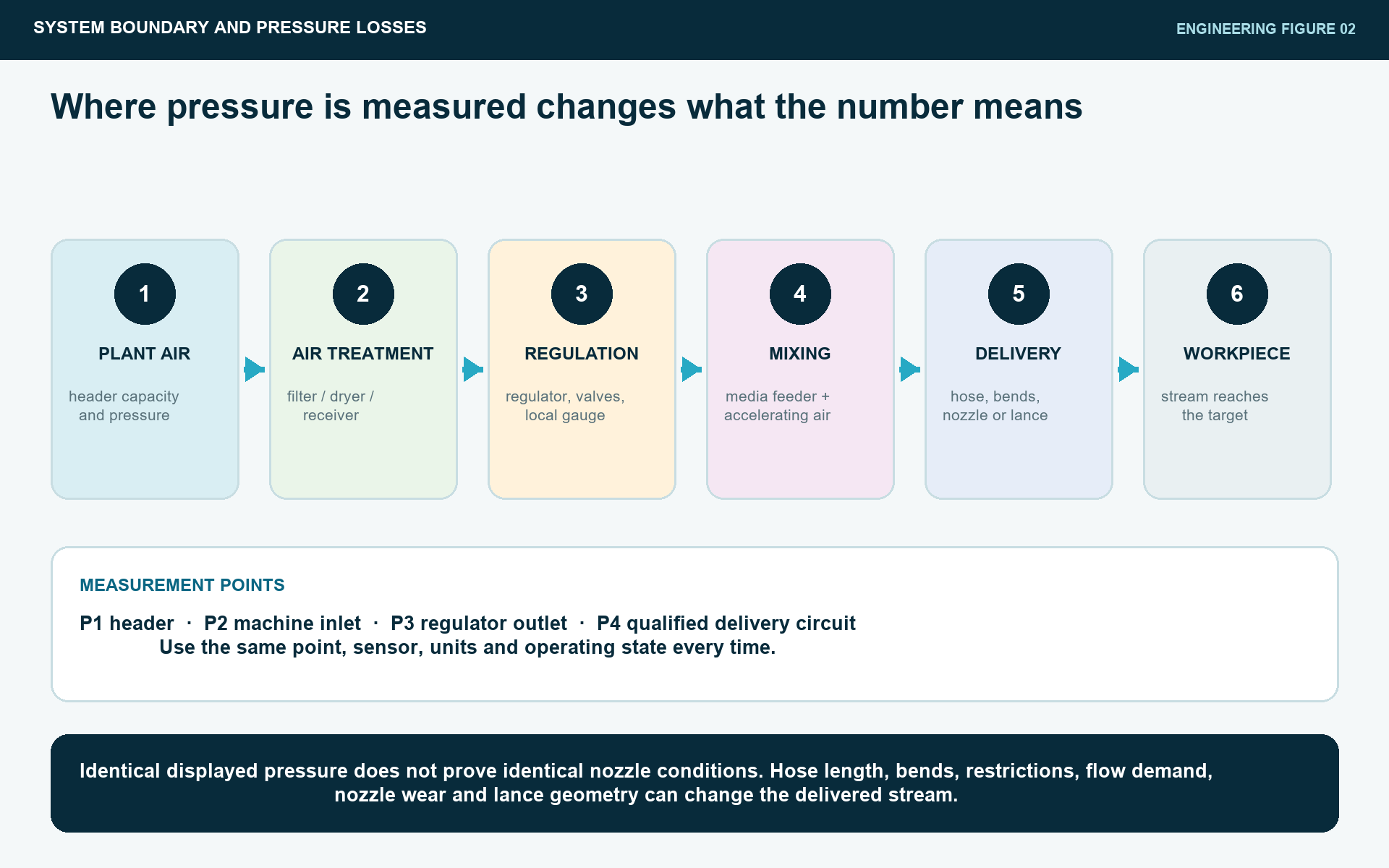
Figure 2. Pressure has meaning only when the measurement point, sensor, units and operating state are defined.
Figure 2 defines the pneumatic system boundary. A regulator display cannot be interpreted without the measurement point, operating flow, restrictions and downstream delivery geometry.
What does air-flow capacity mean during pneumatic shot peening?
Air-flow capacity is the ability of the compressed-air system to supply the required gas flow while the process is operating. A high static pressure with the nozzle closed does not prove adequate capacity after the valve opens and media enters the stream. Receivers, compressor control, pipe diameter, treatment equipment, pressure drop and other plant users can determine whether the process holds its loaded condition.
Volumetric gas flow must include the reference basis. Actual volume at line pressure and standard volume referenced to defined temperature and pressure are not the same quantity. NIST gas-flow standards demonstrate why reference conditions are part of a measurement, not optional metadata. A supplier specification, meter display and plant utility report must use compatible definitions before the values are compared.
ISO 1217 provides acceptance-test methods for compressor volume rate of flow and power, but compressor rating alone does not qualify a shot peening circuit. The machine boundary adds receivers, dryers, filters, valves, hoses and the process demand. Capacity assessment should be performed under a representative loaded condition, including foreseeable simultaneous demand where it can affect the shot peening cycle.
Capacity check: Verify the air system while the released nozzle, feeder and process are operating under representative demand.
How should media mass flow be measured and verified?
Media mass flow should be expressed as delivered mass per unit time and linked to a defined verification method. Depending on the equipment, serial monitoring may use a calibrated sensor while periodic verification uses a timed gravimetric collection. The plan should define collection duration, scale suitability, tare, media state, sampling frequency, acceptance band and response when the result differs from the machine indication.
Feeder command and actual delivery are not the same measurement. A valve position, screw speed or percentage command can remain steady while bridging, moisture, wear, pressure balance or media-size distribution changes the delivered mass. When a command is used for control, the qualified relationship between command and measured delivery should be checked at a defined frequency and after relevant maintenance.
Average flow can conceal pulsation. A process can deliver the correct total mass over one minute while creating alternating high- and low-flux zones during a fast robotic pass. Sensor response, logging rate and averaging should match the process time scale. Where short variation can affect treatment, retain time-resolved evidence or use an independent check that can detect the relevant instability.
Media-flow verification: A stable feeder command is only an input. Verify that the released system delivers the authorized media mass flow with acceptable stability.
How do the nozzle, hose and internal lance change the shot stream?
The nozzle, hose and lance are part of the qualified process because they set restrictions, losses, mixing conditions and stream geometry. Nozzle wear can change internal diameter, acceleration and divergence while pressure and flow remain inside their limits. Hose length, diameter, bends, leakage, routing and connections can also change the condition reaching the nozzle.
An internal lance or deflector usually creates a different pneumatic problem from an open external nozzle. Small passages, bends, replaceable tips and deflection features can add pressure loss and may change the particle-velocity distribution or footprint. The released recipe should identify the actual lance assembly and define inspection, blockage checks and replacement criteria. A generic tool family name is not enough when geometry controls performance.
Stand-off distance and incidence angle act after the stream leaves the nozzle. Research using high-speed imaging has shown that particle velocity can continue to develop outside the nozzle in particular setups. Component geometry then introduces rebound, shadowing and access limits. The machine settings must therefore be qualified with the production delivery arrangement and representative feature geometry.
| Evidence layer | What it can establish | What it cannot prove by itself |
|---|---|---|
| Pressure monitoring | Whether pressure at the instrument location remained inside the authorized band | Nozzle pressure, particle velocity, Almen intensity, coverage or component acceptance |
| Air-flow monitoring | Whether the defined gas delivery remained inside the authorized band and reference basis | Media delivery, stream energy at every particle or treatment of the complete component |
| Media-flow monitoring | Whether delivered shot mass per time remained inside the authorized band | Particle velocity, intensity, access, coverage or surface condition |
| Almen intensity | Whether the stream produced the specified standardized response at the witness setup | Coverage, component residual-stress profile, roughness or geometry access |
| Coverage determination | Whether the specified component surface met the invoked impact-evidence criterion | Intensity, fatigue life, material condition or dimensional conformance |
| Component acceptance | Whether the actual part met the required surface, boundary, cleanliness, dimension and record criteria | Any additional property not named in the drawing or acceptance plan |
Table 2. The measurement location and operating state define what a pressure reading actually represents.
How should pneumatic sensors, sample rates and data handling be specified?
A sensor is useful only when its measurand, location and dynamic behavior match the control question. Define range, accuracy or uncertainty where required, resolution, calibration status, response time, environmental limits and installation. A pressure transmitter selected for slow utility monitoring may not capture a short valve transient. A fast signal can still be made blind by aggressive filtering or long averaging.
Sampling and logging must be considered separately. A controller may sample quickly but store only a one-second average, minimum and maximum. Another system may record every sample but use unsynchronized timestamps across pressure, media flow and robot motion. The control plan should define which data support the interlock, which support batch release and which raw signals must be retained for investigation.
Data integrity includes identity and context. The record should link sensor ID, calibration status, machine, recipe revision, part or batch, cycle start and stop, alarms, overrides, maintenance state and operator or system authorization. A clean trend line without this context cannot prove that the correct component received the approved process.
| Control item | What the specification should define | Change or alarm question |
|---|---|---|
| Pressure point | Exact location, gauge or absolute basis, loaded state, units, normal band and sensor identity | Would the same displayed value represent the same condition after this change? |
| Air delivery | Mass or standard/actual volumetric basis, reference conditions, expected demand and verification method | Can the supply hold the requirement while the full process is flowing? |
| Media mass flow | Mass-per-time basis, verification interval, permissible band, pulsation treatment and media condition | Does the signal represent delivered shot or only a feeder command? |
| Nozzle, lance and hose | Part identity, internal geometry, length, diameter, routing, inspection and replacement limit | Can wear, blockage or configuration change alter the stream inside authorized setpoints? |
| Signal handling | Sample rate, averaging, filter, timestamp, synchronization, resolution and raw-data retention | Could a short excursion disappear inside the displayed average? |
| Reaction plan | Alarm delay, interlock, cycle status, product containment, investigation, approval and restart criteria | What happens to every part exposed during an excursion? |
Table 5. A production record needs clear limits, data context and an agreed reaction when a limit is crossed.
How should alarms and reaction limits be established?
Alarm limits should come from the qualified process window and measurement capability, not from a convenient percentage around the setpoint. The engineering decision should distinguish a warning, controlled deviation, cycle-interrupting alarm and sensor fault. Each state needs a defined delay or persistence rule so normal start-up transients are treated differently from sustained or repeated excursions.
The reaction plan must answer what happened to the part, not only what happened to the machine. Define the exposure interval affected, automatic cycle status, part or batch containment, required data review, reprocessing restrictions, concession authority, investigation and restart evidence. If the system cannot identify which surface was exposed during an excursion, the disposition may need to cover the complete component or lot.
Alarm challenges should be planned where practical. Simulate or safely introduce representative loss of pressure, media flow, sensor signal, utility stability or nozzle/line condition and confirm the system response. A configured alarm that has never been challenged may fail through incorrect scaling, filtering, logic, timestamps or bypass status even though the screen appears normal.
| Observed pattern | Plausible process causes | Immediate control response |
|---|---|---|
| Pressure falls only while peening | Insufficient plant capacity, regulator droop, filter restriction, long hose, leak or simultaneous demand | Contain the affected cycle, compare time traces by measurement point and restore the authorized loaded condition |
| Pressure is stable but Almen response shifts | Nozzle wear, media size or condition, mass-flow change, angle, distance, holder location or sensor bias | Do not raise pressure automatically; check the complete released configuration and independent evidence |
| Average media flow is correct but delivery pulses | Feeder bridging, valve cycling, moisture, poor agitation, sensor filtering or intermittent line restriction | Review time-resolved data, verify delivery gravimetrically and correct the feeder or media condition |
| Coverage develops more slowly | Lower particle flux, larger footprint, increased distance, geometry shadowing, motion change or media degradation | Stop recipe transfer, confirm access and re-establish qualified exposure on representative geometry |
| Nozzle pressure differs between machines | Different sensor locations, regulator behavior, hose losses, nozzle geometry, air capacity or reference basis | Treat the machines as different systems until equivalence is demonstrated and approved |
| Short spikes appear in logged signals | Valve transients, sensor dynamics, electrical noise or real pneumatic instability | Preserve raw data, establish whether the event is physical and apply the authorized alarm and product-reaction logic |
Table 3. Common instability symptoms point to different pneumatic, feeder, media or delivery-system checks.
Product reaction: Every pneumatic excursion needs a defined part disposition, authorized restart condition and traceable record.
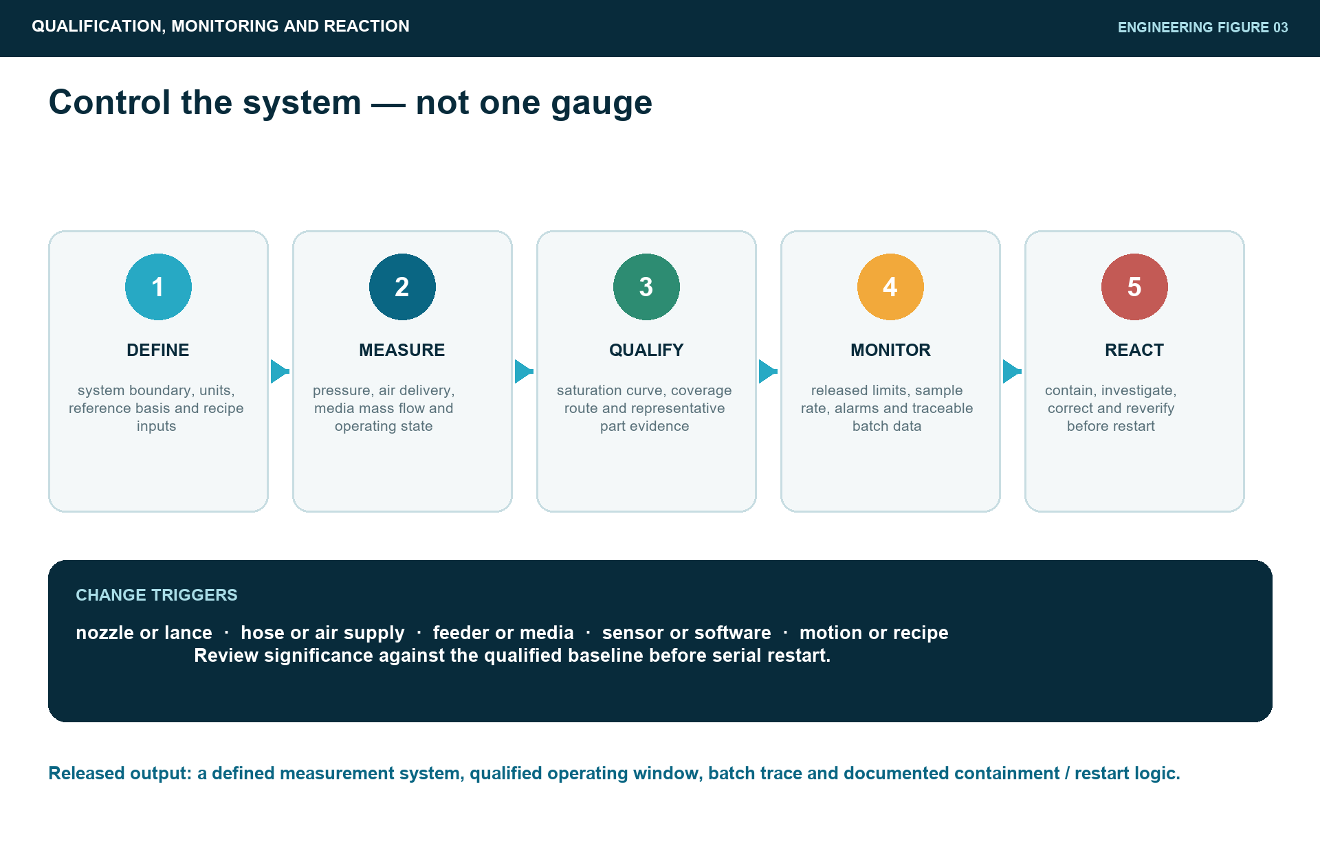
Figure 3. A released pneumatic process controls the complete system, not one gauge.
Figure 3 connects definition, measurement, qualification, monitoring and reaction. A change to the air supply, feeder, media, hose, nozzle, lance, sensor, software, motion or recipe must be reviewed against the qualified baseline.
How is a pneumatic shot peening process qualified?
Qualification should reproduce the serial equipment boundary, media, feeder, hose, nozzle or lance, fixture, distance, angle, motion, masking and measurement system. Develop stable pressure, air delivery and media-flow ranges before claiming a production window. Then establish the specified Almen intensity and the component exposure, coverage and acceptance route with representative geometry.
The trial should examine combinations, not isolated setpoints. A pressure at the lower band with high media loading may behave differently from the same pressure with low loading. The upper pressure band with a worn nozzle may also differ from the nominal setup. Choose trials that test the edges and interactions relevant to the process risk without treating experimentation as authorization to exceed the component requirement.
The accepted result must become a controlled baseline. Record the released setup, settings, allowed ranges, signal handling, verification frequency, motion, component exposure, inspection, alarms and change triggers. Serial production reproduces this baseline. Maintenance or software changes that can affect the pneumatic circuit, feeder, data path or motion need formal review before the process returns to service.
| Stage | Required engineering action | Objective output |
|---|---|---|
| 1. Define the boundary | Identify compressor or utility, treatment, receiver, regulators, valves, hoses, feeder, nozzle or lance, sensors and control software | Controlled pneumatic-system diagram and equipment identity |
| 2. Define measurements | Set location, units, reference conditions, calibration, range, response time, filtering, sample rate and data retention | Measurement plan with interpretable values |
| 3. Establish stable inputs | Develop pressure, air delivery and media-flow ranges on the actual production configuration | Repeatable loaded operating window |
| 4. Qualify stream response | Develop the specified saturation curve or intensity verification at released witness locations | Approved Almen intensity basis |
| 5. Qualify component delivery | Establish access, coverage, motion, exposure, surface and dimensional acceptance on representative geometry | Accepted component trial and production exposure |
| 6. Freeze serial control | Release setpoints, tolerances, alarms, interlocks, recipes, inspection, records and operator actions | Controlled work instruction and reaction plan |
| 7. Challenge the system | Test representative utility demand, start-up, restart, empty feeder, blocked line, sensor fault and maintenance conditions where applicable | Verified detection and safe product disposition |
| 8. Control changes | Review nozzle or lance replacement, hose routing, feeder, utility, software, sensor, site and process changes | Approved change history and requalification decision |
Table 4. Qualification links defined inputs, standardized Almen response, coverage and representative component evidence.
How do pneumatic inputs relate to Almen intensity and coverage?
Pneumatic inputs control how the machine creates the stream; Almen intensity checks the standardized response of that stream at defined witness locations. SAE J443_202512 defines the method for deriving and verifying peening intensity, while SAE J442_202602 defines requirements for the associated tools and supplies. The current invoked drawing and process specification still determine the required strip, intensity range, locations and frequency.
Coverage answers a different question on the component surface. SAE J2277_202301 provides procedures for determining coverage and relating it to part exposure. A process can pass pressure, air-flow, media-flow and Almen checks yet still miss a recessed feature because access, motion, angle or shadowing is wrong. Conversely, visible coverage does not validate the intensity or pneumatic record.
Component acceptance closes the route. It may include masking boundaries, visible surface condition, cleanliness, roughness, dimensions, retained-media removal and special evidence required by the contract. Pressure and flow monitoring strengthen traceability, but they cannot replace an inspection or test assigned to the actual component.
Evidence boundary: Inputs, Almen intensity, coverage and component acceptance support one process, but each proves a different fact.
How does compressed-air quality affect pneumatic shot peening?
Compressed-air contamination can affect valves, sensors, feeders and the stability of media delivery. Water can promote media agglomeration, corrosion or line blockage depending on the media and system. Oil and particles can contaminate equipment or the component surface. The required air quality should therefore be defined from the process, equipment and downstream acceptance needs.
ISO 8573-1 classifies compressed-air purity for particles, water and oil, but the article should not assign a universal class to every shot peening process. The contract, equipment manufacturer, media, component and qualification establish the applicable requirement. The sampling location also matters because a compliant plant header does not automatically prove the condition at the machine or nozzle circuit.
Routine control can include dryer and filter status, drainage, differential pressure, dew-point or contamination checks where required, along with maintenance and reaction criteria. Air-treatment changes should be reviewed as process changes when they can affect delivery stability, contamination or component acceptance.
What signs show that a pneumatic shot peening process is unstable?
A process is unstable when its delivered stream or evidence changes more than the authorized window, even if the average setpoint appears correct. Warning signs include pressure droop under load, repeated regulator hunting, media-flow pulsation, feeder bridging, nozzle wear, unexplained Almen drift, longer coverage development, inconsistent footprint and alarms that occur only during specific robot positions or plant demand.
Troubleshooting should preserve the configuration and evidence before adjustments are made. Save synchronized pressure, flow, alarm and motion data; identify the affected parts; inspect nozzle, lance, hose, feeder and media; confirm sensor calibration and signal scaling; then repeat the authorized verification. Turning up pressure can hide one symptom while creating a different surface or equipment risk.
The process is not ready for release when the measurement location is unknown, units or reference conditions are missing, setpoints were copied from another machine, a feeder command is treated as measured flow, alarms have no part-reaction rule, the nozzle identity is uncontrolled or coverage cannot be verified on the critical feature.
- Pressure is recorded without a measurement point, gauge/absolute basis or loaded operating state.
- Air-flow values omit reference temperature and pressure or mix actual and standard volume.
- Media flow is represented only by valve position, screw speed or percentage command.
- Nozzle, lance, hose or feeder changes can occur without engineering review.
- Averages are stored but raw variation, alarms and timestamps needed for investigation are lost.
- The reaction plan stops the machine but does not define product containment and restart authority.
What should an RFQ for pneumatic shot peening contain?
A useful RFQ starts with the controlled drawing, revision and every invoked shot peening document. Mark the treatment, masking, transition and prohibited zones. State the material and heat-treatment condition, required Almen intensity and strip, coverage or additional exposure, permitted media, component quantities, delivery target and required records.
For pneumatic process review, add any equipment or monitoring constraints, internal features, lance requirements, nozzle access limits and customer-specific data expectations. If pressure, media flow, air quality, monitoring or alarm requirements are already contractually defined, include their revisions and measurement basis. If they are not defined, identify them as engineering questions instead of inserting assumed universal limits.
SP Center can review the supplied package and confirm whether the requested pneumatic shot peening route, evidence and schedule are feasible within the applicable capability and approval scope. Send the controlled documents to [email protected] or call +48 519 772 773. The quotation should then identify open technical questions, trial needs, production assumptions, records and any customer approval required before serial processing.
FASTEST USEFUL ENQUIRY Send the drawing, complete shot peening requirement, marked zones, material condition, quantity, target date and required evidence to [email protected] or call +48 519 772 773.
Which assumptions about air pressure and flow should be avoided?
The assumption that pressure is the shot peening intensity is incorrect. Pressure is a pneumatic input; Almen intensity is a standardized measured response derived with the prescribed strip, holder, gage and procedure.
The assumption that a higher pressure always produces a better result is incorrect. The authorized component process window governs; excessive severity or an unsuitable combination can damage surface condition or change the intended response.
The assumption that regulator pressure is pressure at the nozzle is incorrect. Measurement location and dynamic losses through the active system determine what the value represents.
The assumption that correct media flow proves correct coverage is incorrect. Access, distance, angle, footprint, motion and qualified exposure still determine treatment of the component surface.
The assumption that a stable average proves a stable cycle is incorrect. Pulsation and short excursions can disappear inside averaging, filtering or a slow logger.
The assumption that identical pressure and flow setpoints make two machines equivalent is incorrect. Utility, regulators, hoses, feeders, nozzles, sensors and motion must be shown to reproduce the approved process.
The assumption that alarms are only maintenance information is incorrect. An excursion can affect product; the reaction plan must identify containment, evaluation, authority and restart evidence.
Frequently asked questions about pressure and flow in pneumatic shot peening
Does higher air pressure always increase shot peening intensity?
Higher pressure can increase particle velocity and Almen response in a fixed pneumatic configuration, but the relationship is not universal. Nozzle, media, mass flow, distance and system losses change the result, so use the specified intensity and qualified machine window.
Where should air pressure be measured on a shot peening machine?
Measure pressure at the location defined by the qualified control plan. Plant header, machine inlet, regulator outlet and near-delivery measurements answer different questions and should not be treated as interchangeable.
What is the difference between air flow and media flow?
Air flow describes gas delivery, while media flow describes the mass of shot delivered per unit time. They interact in the nozzle system but require separate units, sensors or verification methods and acceptance limits.
Can feeder percentage be used as media mass flow?
Only when the released process establishes and maintains a verified relationship between that command and delivered mass per time. Periodic calibrated or gravimetric verification is still needed at the frequency required by the control plan.
Why can Almen intensity change when pressure looks stable?
Almen intensity can shift because media condition, mass flow, nozzle wear, distance, angle, witness location or sensor bias changed. Investigate the complete configuration instead of adjusting pressure automatically.
How should pneumatic shot peening alarms be set?
Set alarms from the qualified process window, measurement capability and product risk. Define persistence or delay, cycle response, affected-product containment, investigation, approval and restart criteria.
Does compressed-air quality matter in shot peening?
Yes. Water, oil or particles can affect valves, sensors, media delivery and component cleanliness. Use the air-quality requirement defined by the equipment, process, component and governing documents rather than a universal class.
What does SP Center need to review pneumatic shot peening work?
Send the controlled drawing and process documents, material condition, marked treatment and masking zones, Almen and coverage requirements, media restrictions, quantities, delivery target and required records to [email protected] or call +48 519 772 773.
Key takeaways
- Keep air pressure, air delivery, media mass flow, particle behavior and Almen intensity as separate quantities.
- Attach measurement point, operating state, units and reference conditions to every pressure and gas-flow value.
- Develop pressure and media flow together on the actual feeder, hose, nozzle or lance and motion configuration.
- Treat nozzle wear, hose routing, utility demand, air quality, sensor behavior and signal handling as process controls.
- Use Almen intensity, coverage and component acceptance as independent evidence alongside machine-input monitoring.
- Link every alarm to product containment, investigation, authorized restart and traceable records.
- For an SP Center feasibility review, contact [email protected] or +48 519 772 773.
Related SP Center shot peening guides
- What Is Shot Peening – How It Works and When to Use It – core mechanism and application screening
- Almen Intensity in Shot Peening – standardized intensity determination and verification
- 100% vs 200% Shot Peening Coverage – coverage and additional-exposure control
- Shot Peening Process Step by Step – end-to-end development and production sequence
- 12 Common Mistakes in Shot Peening Specifications – requirements, evidence and change-control errors
- How to Choose a Shot Peening Supplier for Critical Parts – supplier qualification and RFQ evidence
Technical references
1. SAE AMS2430U: Shot Peening, revised April 2018
2. SAE AMS2432E: Shot Peening, Computer Monitored, revised October 2022
3. SAE J2441_202511: Shot Peening, stabilized November 2025
4. SAE ARP7488: Peening Design and Process Control Guidelines, issued January 2018
5. SAE J442_202602: Tools for Peening Intensity Determination and Verification, revised February 2026
6. SAE J443_202512: Procedures for Determining and Verifying Peening Intensity, revised December 2025
7. SAE J2277_202301: Shot Peening Coverage Determination, revised January 2023
8. SAE J2597_201709: Computer Generated Shot Peening Saturation Curves
9. SAE AMS2431E: Peening Media, General Requirements, revised April 2023
10. ISO 1217:2009: Displacement Compressors – Acceptance Tests, confirmed 2021
11. ISO 8573-1:2010: Compressed Air – Contaminants and Purity Classes
12. NIST, Pressure and Gas Flow Unit Conversions, updated July 2025
15. Ogawa et al., Measurement and Analysis of Shot Velocity in Pneumatic Shot Peening, 1994
16. SP Center, shot peening service
Before you request a pneumatic shot peening quotation
- Controlled drawing, revision and complete shot peening document hierarchy.
- Marked treatment, masking, transition and prohibited zones, including internal or difficult features.
- Material and heat-treatment condition, Almen intensity and strip, coverage or exposure and permitted media.
- Pneumatic equipment boundary, nozzle or lance identity, hose configuration and any customer monitoring constraints.
- Required pressure, air-flow and media-flow measurement basis where contractually defined.
- Qualification, FAI, PPAP, inspection, record, certificate, packaging and customer-approval requirements.
- Prototype and serial quantities, batch pattern, delivery target and contact number +48 519 772 773.
Applicable revisions: The contractually invoked document and revision govern the part. Current publisher status does not replace an invoked revision or customer flow-down without authorized approval.
Pneumatic shot peening support from SP Center
SP Center supports pneumatic shot peening RFQ review, system-boundary and measurement review, Almen intensity development and verification, media and machine control, coverage review, trial and qualification planning, controlled serial processing, traceability and reporting against confirmed engineering requirements.
SP Center – We strengthen what matters.
Shot peening service: spcenter.pl/en/services/shot-peening/
SP Center Sp. z o.o. | ul. Biznesowa 5, 35-213 Rzeszow, Poland | [email protected] | +48 519 772 773
Author: Paweł Kmieć