


Compare mechanisms, residual-stress depth, surface response, access, process controls, qualification evidence and industrial selection criteria
Conventional shot peening and laser peening can both be used to introduce compressive residual stress, but they are not interchangeable process variants. Conventional shot peening accelerates controlled solid media against a surface and qualifies the peening stream through the Almen system together with coverage and media controls. Laser peening uses computer-controlled pulsed laser-induced shock loading under a separate process route. Selection must be based on the actual material, geometry, failure mechanism, required stress profile, surface limits, production demand and approval basis.
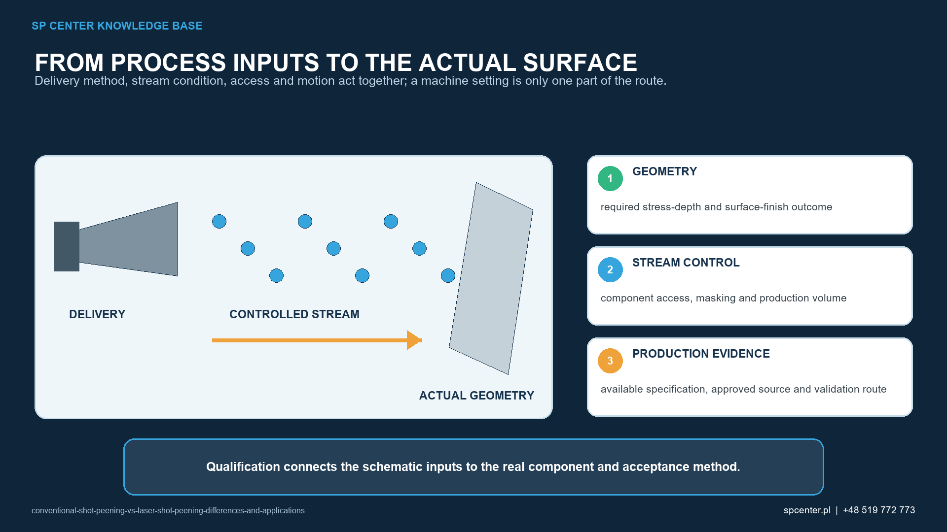
What is the main difference between conventional shot peening and laser peening?
Conventional shot peening creates many small impacts. Each particle produces a local indentation and plastic strain while the constrained subsurface responds elastically. A controlled pattern of repeated impacts can leave a beneficial compressive residual-stress field, provided the material, media, intensity, coverage and geometry are qualified.
Laser peening, also called laser shock peening, directs short laser pulses onto controlled surface locations. The laser-material interaction creates a high-pressure pulse that launches a stress wave into the component. Qualified routes can use surface-preparation layers and a confinement medium to manage that interaction. These are controlled elements of the laser route, not universal accessories that may be added or removed informally.
| Comparison area | Conventional shot peening | Laser peening |
|---|---|---|
| Energy transfer | Accelerated shot repeatedly strikes the surface and produces local plastic deformation | Pulsed laser energy generates a short-duration pressure wave that plastically strains the near-surface material |
| Delivery system | Air-blast nozzle, lance or centrifugal wheel with controlled media and part motion | Computer-controlled optical delivery, pulse pattern and part or beam motion |
| Principal process controls | Media type, size, hardness, shape and condition; Almen intensity; coverage; flow; speed or pressure; geometry and exposure | Laser energy and pulse characteristics, illuminated area, pulse pattern and overlap, focus or working distance, surface preparation and any qualified overlay or confinement system |
| Surface evidence | Impact coverage and surface condition assessed by the approved method | Qualified pulse-field placement, overlap and surface-condition evidence defined by the laser process specification |
| Typical surface response | A dimpled impact texture with roughness and possible dimensional effects that depend on the qualified route | A route-dependent surface response influenced by pulse loading, surface preparation and any sacrificial layer; it is not automatically damage-free or smoother |
| Standards framework | For example AMS2430 or AMS2432 when contractually invoked, together with drawing and customer requirements | For example AMS2546A when contractually invoked, together with drawing and customer requirements |
Table 1. The processes share a possible engineering objective but use different energy delivery, controls and acceptance evidence.
How do the residual-stress profiles compare?
Either process can create surface or near-surface compressive residual stress. The achieved magnitude, depth, balance and stability depend on the material, prior manufacturing condition, geometry and the complete qualified process. Published laser-peening applications can show a deeper affected layer than conventional shot peening, but that observation is not a guarantee for every alloy, section or component.
The engineering question is not simply which process is deeper. The relevant profile must be compatible with the expected crack-initiation site, applied stress gradient, surface condition, later thermal or mechanical operations and dimensional stability. Excessive or poorly balanced processing can be unacceptable even when compressive stress is measured.
How does surface condition differ?
Conventional shot peening forms a characteristic impact texture. Media diameter and shape, hardness, intensity, angle, exposure and incoming finish influence roughness, local folding, edge response and dimensional risk. Coverage describes whether the required surface has received the specified impact pattern; it does not by itself prove residual-stress depth or fatigue performance.
Laser peening does not use loose shot, but that does not make its surface outcome automatically unchanged or superior. Pulse loading, laser spot edges, surface preparation, any sacrificial layer, cleaning and the underlying material can affect the final surface. Each route needs its own damage, finish, cleanliness and dimensional acceptance criteria.
Are Almen intensity and coverage applicable to both processes?
No direct equivalence should be assumed. In conventional shot peening, Almen intensity is derived from a saturation curve produced with the specified strip and holder arrangement. It verifies the capability of the peening stream under that test configuration. Coverage is assessed separately on the required component surface using the approved method.
Laser peening controls laser energy and pulse characteristics, illuminated area, pulse placement and overlap, delivery geometry and other variables defined by its qualified route. A laser pulse pattern must not be labelled 100% or 200% conventional shot-peening coverage unless the governing laser specification expressly defines and accepts that terminology. Equating Almen arc height with laser loading would obscure the real controls.
Which process offers better access to complex parts?
Access depends on the actual feature. An air-blast nozzle or lance can be directed toward radii, bores or cavities when size, stand-off, angle, rebound, shadowing and media removal are manageable. A wheel system can deliver high throughput on suitable exposed geometries but has a different stream envelope and control architecture.
Laser peening needs a controlled optical path, working distance, focus and pulse-field placement. Mirrors, optics or specialized handling may extend access, but internal features, steep transitions, mask boundaries and hidden zones remain application-specific constraints. A drawing review and worst-case trial are necessary for both technologies.
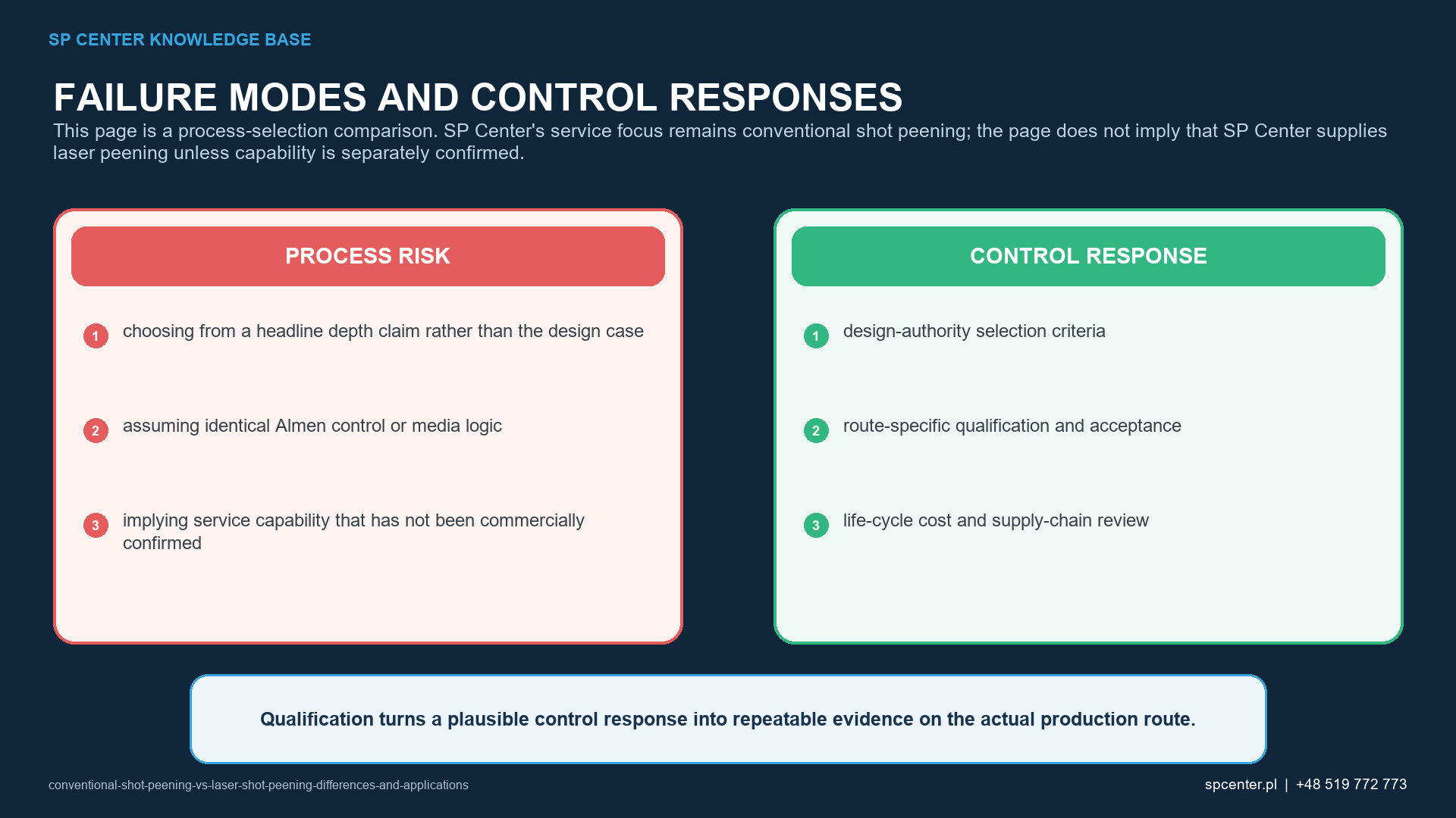
How should an engineer choose between the two processes?
| Selection question | Why it matters | Evidence needed before release |
|---|---|---|
| What failure mechanism is being addressed? | Surface crack initiation, fretting, foreign-object damage, corrosion-assisted fatigue and other mechanisms do not respond identically | Design or process authority rationale linked to the component duty and material condition |
| What residual-stress profile is required? | Depth, magnitude, stability and balance can matter more than the process label | Qualified development data and, where invoked, representative XRD or other validated measurement |
| Which surfaces are accessible? | Nozzle, wheel or lance access differs from optical line of sight, focus and pulse placement | Worst-case geometry trial with treatment boundaries, masks and motion represented |
| What surface and dimensional limits apply? | Both routes can alter surface condition or part response | Roughness, damage, distortion, dimensional and cleanliness acceptance as required |
| Which approval route governs? | A process cannot be substituted merely because both generate compressive residual stress | Current drawing, specification revision, approved source, qualification and customer authorization |
| What production demand must be met? | Cycle time, batch size, automation, maintenance, consumables and supply-chain capacity affect the industrial route | Demonstrated capacity and a controlled serial release plan, not an unsupported cost assumption |
Table 2. Selection is a controlled engineering decision supported by component evidence, not a generic comparison of process names.
Conventional shot peening is widely established for serial treatment of springs, gears, shafts, blades, structural parts and many other fatigue-critical components. It can offer flexible equipment choices and mature media, intensity and coverage controls. Those advantages do not remove the need for part-specific masks, fixtures, access qualification or acceptance.
Laser peening may be selected where its qualified stress profile, surface route or automation is justified by the application. Equipment, optical access, surface-system logistics, capacity and approved-source availability must be included in the decision. Unsupported claims that one route is always cheaper, faster or more effective should not drive a specification.
Can one process replace the other on an existing drawing?
No unilateral substitution is acceptable. A drawing invoking shot peening, an AMS specification, customer source approval or validated fatigue basis establishes a process identity. Changing to laser peening can alter the stress profile, surface, qualification method, equipment, supplier approval and release evidence. The design authority and contractual authority must approve the change before production.
The reverse change requires the same discipline. Matching one residual-stress reading or obtaining a visually acceptable surface does not demonstrate equivalent fatigue, corrosion, distortion or lifecycle performance.
What do AMS2430, AMS2432 and AMS2546A cover?
SAE presents AMS2430 as a shot-peening specification and AMS2432 as a specification for computer-monitored shot peening. Their complete, contractually invoked revisions govern conventional-process requirements. The Almen tools and procedures are addressed separately by SAE J442 and J443, and conventional shot-peening coverage by SAE J2277.
SAE describes AMS2546A as covering computer-controlled laser peening of metal part surfaces to induce residual compressive stress at and beneath the surface. This public scope does not justify inventing detailed acceptance clauses. The purchased standard, drawing, customer flow-down and approved process documentation must be read together.
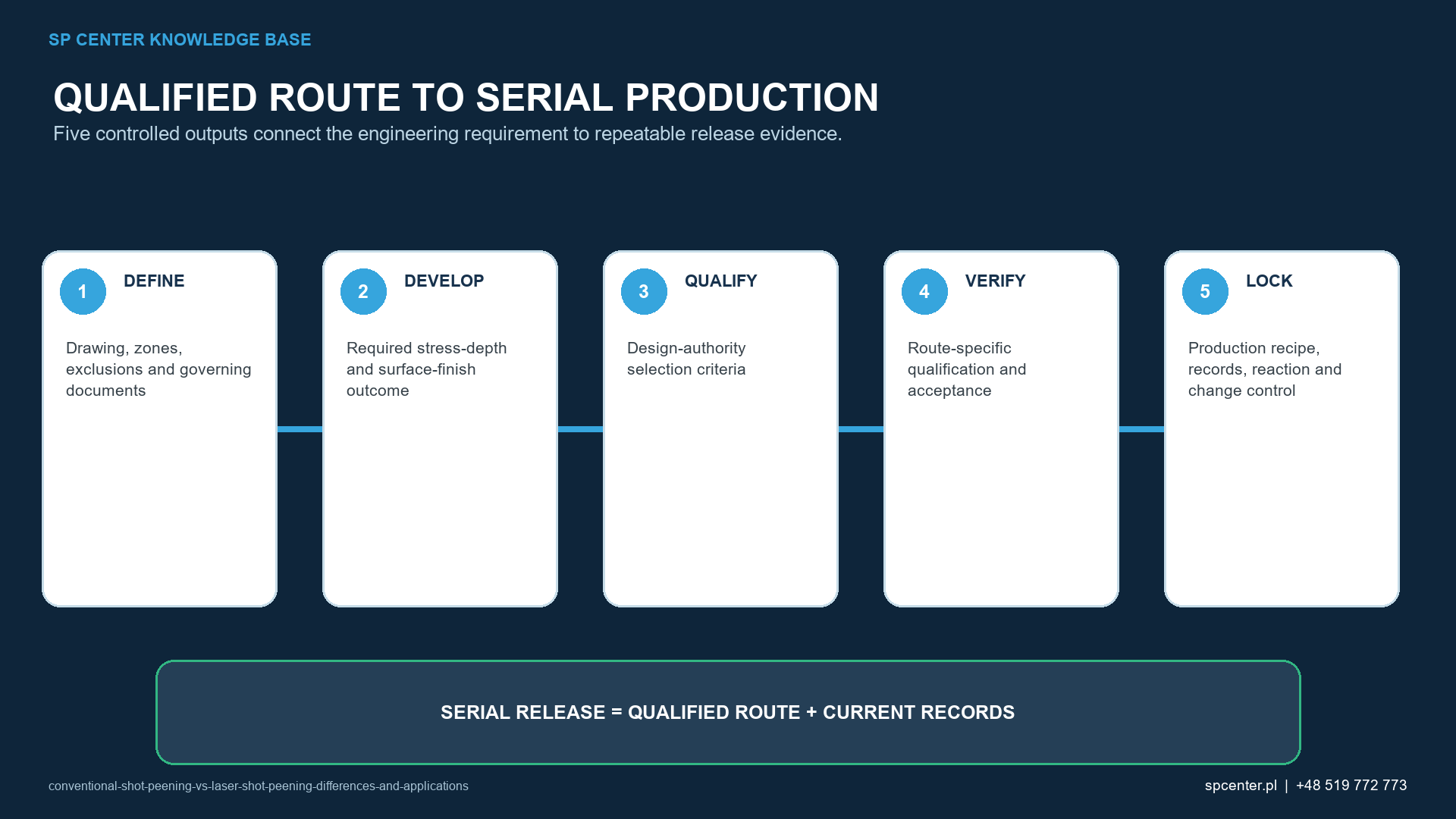
What evidence is needed for qualification and production?
| Control stage | Conventional shot peening evidence | Laser peening evidence |
|---|---|---|
| Requirement review | Defined treatment zones, exclusions, full Almen range and strip designation, coverage, media and acceptance requirements | Defined treatment zones, exclusions, laser process specification, pulse-field and surface-system requirements, and acceptance criteria |
| Development | Equipment, media, fixture, masks, part motion, exposure and worst-case access | Equipment and optics, pulse route, surface preparation, any overlay and confinement, fixture, masks and worst-case access |
| Process qualification | Saturation-curve basis, Almen setup, coverage method and component-specific validation when required | Qualified laser parameters, pulse placement and overlap, representative component validation and specified monitoring |
| Production monitoring | Media condition, flow, air pressure or wheel speed, motion, exposure, alarms and required Almen verification | Laser and delivery-system parameters, pulse path, focus or working distance, surface-system status, motion, alarms and required verification |
| Part acceptance | Coverage, boundary, damage, cleanliness, dimensions and other invoked inspections | Pulse-field or treatment-zone acceptance, surface condition, dimensions and other invoked inspections |
| Change control | Requalify changes that can alter stream energy, access, media, motion, exposure or acceptance | Requalify changes that can alter laser loading, optics, pulse pattern, surface system, access, motion or acceptance |
Table 3. Similar evidence headings do not make the underlying measurements interchangeable.
How should residual stress and fatigue performance be validated?
X-ray diffraction with material removal, another validated depth-profile method, fatigue testing or a combination may be invoked during development. Measurement uncertainty, removal method, stress redistribution, location and orientation must be controlled. One surface value cannot characterize an entire depth profile or establish process equivalence.
Fatigue comparisons require representative material, geometry, surface condition, load ratio, environment and sufficient specimens. The result remains bounded by the test basis. Production release should use the controls defined by the approved route; destructive residual-stress or fatigue testing is not automatically a batch-release test unless the contract requires it.
What information should an RFQ contain?
- Controlled drawing, revision, part number and governing specification hierarchy.
- Material, heat treatment, hardness, prior operations and incoming surface condition.
- Marked treatment, exclusion and transition zones plus critical dimensions.
- Required residual-stress, surface, fatigue or distortion outcome and the authority that defines it.
- For conventional shot peening: full Almen range and strip designation, coverage, media restrictions and acceptance method.
- For laser peening: invoked laser specification, qualified pulse-field and surface-system requirements, and acceptance method.
- Qualification, source approval, first-article, production records and change-control expectations.
- Part size, mass, lot pattern, annual demand, packaging and target date.
Frequently asked questions
Is laser peening always better than conventional shot peening?
No. The appropriate route depends on the material, geometry, failure mechanism, required residual-stress profile, surface and dimensional limits, production demand, specification and customer approval. A deeper compressive layer reported for some laser-peened applications does not create a universal ranking.
Does conventional shot peening always produce a shallower compressive layer?
Not as an unconditional rule. The resulting profile depends on material condition, media, intensity, coverage, geometry and other qualified variables. Compare measured or validated profiles for the actual application rather than process names alone.
Is Almen intensity used to control laser peening?
The Almen system is established for conventional peening-stream intensity. It must not be transferred to laser peening as an equivalent control unless the governing laser process document explicitly defines such a use. Laser peening has its own qualified parameters and evidence.
Does 100% or 200% coverage mean the same thing for both processes?
No. In conventional shot peening, coverage concerns the proportion of a surface showing impact evidence and additional coverage can be specified through exposure time. Laser peening controls a qualified pulse field and overlap. The terminology and acceptance method of the governing laser specification must be used.
Can a drawing call for conventional shot peening be processed by laser peening instead?
Not without authorization. The technologies have different mechanisms, controls, specifications and qualification evidence. A substitution requires design and contractual approval plus the qualification or validation required by the controlling documents.
Does laser peening require a coating or water layer?
Some qualified laser peening routes use a sacrificial or ablative overlay and a transparent confinement medium, but the exact surface system is process- and specification-dependent. It should not be generalized or changed outside the approved route.
Which process is more suitable for complex internal geometry?
Neither has universal access. Conventional systems may use nozzles or lances, while laser delivery requires a controlled optical path and pulse placement. The actual bore, cavity, radius, mask and line-of-sight conditions must be demonstrated.
Does SP Center provide laser peening?
SP Center specializes in controlled conventional shot peening. We can review a drawing and conventional shot peening requirement; this article does not represent an offer of laser peening services.
Key takeaways
- Conventional shot peening and laser peening use different energy-delivery mechanisms.
- Almen intensity and conventional impact coverage are not universal laser-process metrics.
- Neither process is automatically superior for every alloy, feature or failure mechanism.
- Surface response, access, stress depth, capacity and approvals must be evaluated together.
- A process substitution requires formal authority and application-specific qualification.
- Production evidence must remain traceable to the selected process and current governing documents.
Related SP Center guides
- How Shot Peening Influences Fatigue Life
- How to Read a Residual-Stress Depth Profile
- Shot Peening Repeatability
Technical references
1. SAE AMS2430U: Shot Peening, revised April 2018
2. SAE AMS2432E: Shot Peening, Computer Monitored, revised October 2022
3. SAE AMS2546A, Laser Peening
4. SAE J442_202602: Tools for Peening Intensity Determination and Verification, revised February 2026
5. SAE J443_202512: Procedures for Determining and Verifying Peening Intensity, revised December 2025
6. SAE J2277_202301: Shot Peening Coverage Determination, revised January 2023
Standards note: The complete revisions, drawing, approved process and customer-specific requirements invoked by the contract govern.
Author: Paweł Kmieć
Discuss a conventional shot peening requirement: +48 519 772 773 | [email protected]