


Connect drawing-defined zones, high-strength material, grinding and coating sequence, feature access, customer approvals and full traceability
Landing-gear shot peening is a controlled special process used on design- or repair-defined surfaces where fatigue or stress-corrosion performance is sensitive to the near-surface condition. Fillets, bores, lugs, transitions and internal features can be difficult to reach and inspect. Material state, prior machining or grinding, coating sequence, masking, Almen intensity, coverage, source approval and serial traceability must therefore be reviewed as one route—not as a generic aerospace recipe.
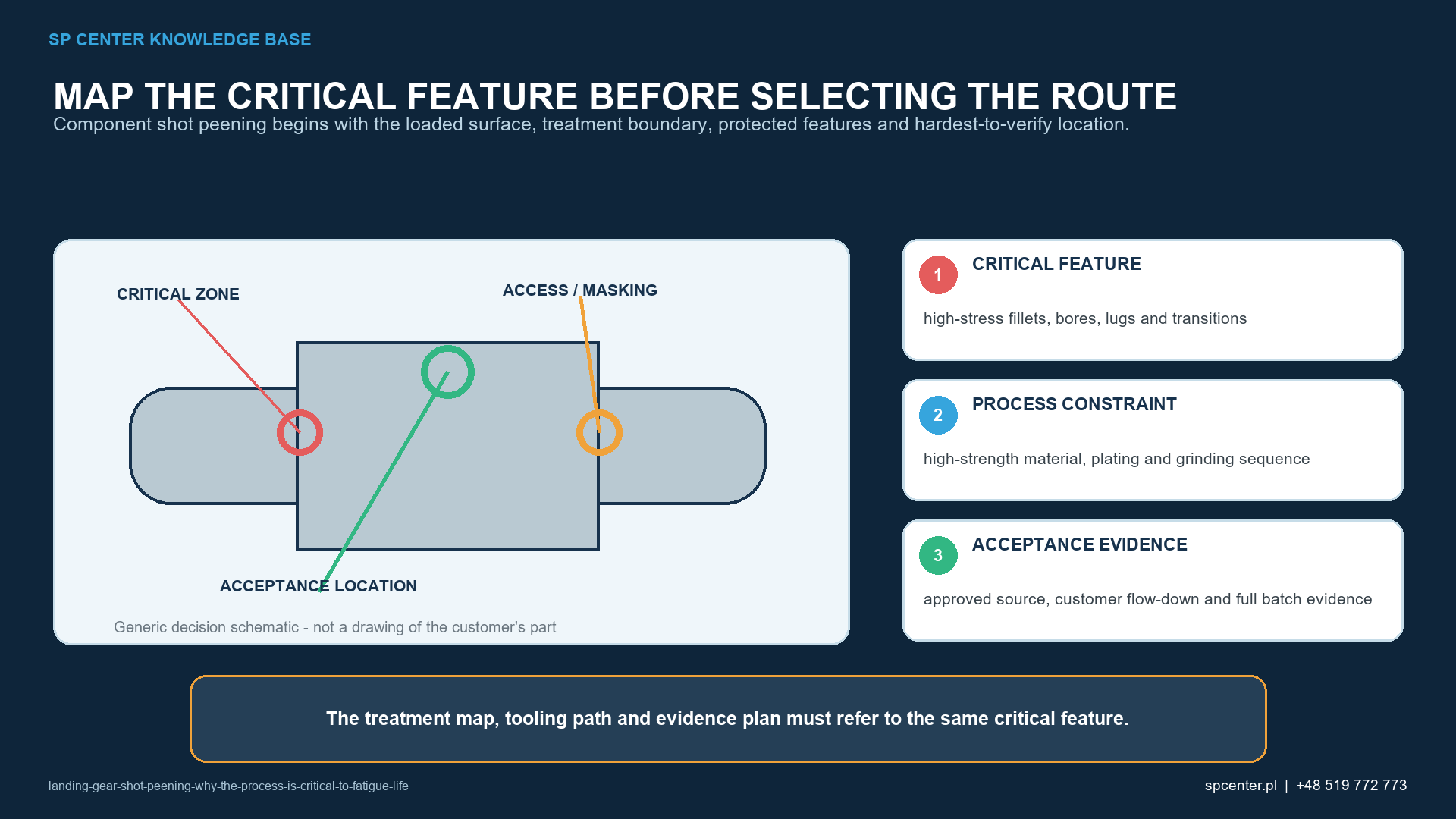
Where is shot peening used on landing-gear components?
Possible applications include defined regions of cylinders, axles, pins, piston rods, torque links, lugs, eyes, bores and diameter transitions. The list is illustrative. Treatment zones, boundaries and exclusions come from the controlled drawing, component maintenance data or approved repair scheme.
| Landing-gear feature | Potential process challenge | Required control basis |
|---|---|---|
| Fillets and diameter transitions | High stress concentration and changing incidence angle | Drawing-defined zone, representative fixture, motion and coverage method |
| Bores and internal radii | Restricted access, shadowing and difficult visual examination | Qualified nozzle or stream access and approved direct or indirect coverage assessment |
| Lugs, eyes and attachment features | Masking boundary, edge severity and local geometry | Controlled treatment map, mask condition and feature-specific acceptance |
| Ground or machined surfaces | Grinding burn, cracks, laps or tool damage can pre-exist | Required pre-peening inspection and engineering disposition of defects |
| Plated or coated surfaces | Sequence, contamination and rework restrictions | Approved manufacturing or repair route and coating-specific flow-down |
| Serialised repair part | Configuration and life history may differ from new production | Part identity, work order, repair scheme, prior operations and customer authority |
Table 1. Qualification and acceptance follow the feature and component condition actually invoked.
Why is the incoming surface condition critical?
High-strength steel, titanium and aluminium landing-gear parts have different surface, contamination and damage sensitivities. A peening process cannot convert a crack, grinding burn, fold, lap, corrosion pit or unauthorised material removal into an acceptable part. Complete the required inspection and technical disposition first.
Incoming hardness, heat treatment, dimensions, roughness, coating-removal state, cleaning and customer-specified inspections outside SP Center's service scope are controlled only where the governing documents require them. Do not add or omit an inspection based on a generic article.
How does the manufacturing or repair sequence affect the result?
Machining, grinding, stress relief, coating removal, inspection, peening, cleaning and nickel, chromium or other coating operations can interact. The approved order is part-specific. A changed repair depth, heat treatment, intermediate finish or coating system can invalidate the previous process basis.
Before starting, freeze the drawing or repair-instruction revision, purchase-order clauses, customer flow-down and complete revisions of invoked specifications. If a document is missing or conflicts with another, stop and obtain a controlled clarification from the responsible authority.
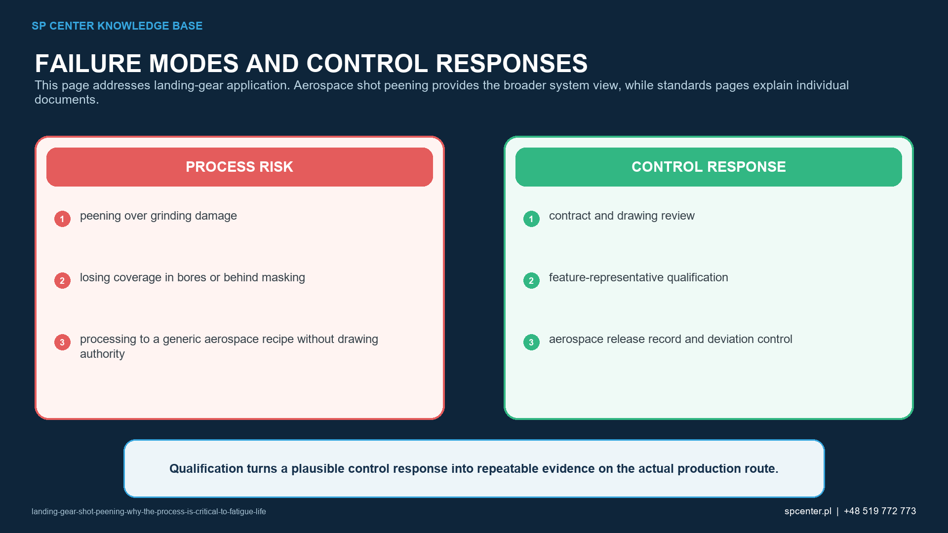
How are difficult bores, fillets and masking boundaries qualified?
Use production-representative geometry, equipment, media, fixture, mask, program and motion. Demonstrate access at the least favourable required feature. A generic Almen position outside the bore cannot by itself prove that the bore wall received the specified impact coverage.
Intensity verification uses the invoked Almen system and properly determined saturation curve. Coverage is examined on the specified component surface by the approved method. Fluorescent or tracer methods are indirect and require approval, qualification and correlation to the applicable acceptance basis.
How do Nadcap and customer approvals fit together?
| Approval or evidence layer | What it establishes | What it does not establish alone |
|---|---|---|
| Nadcap accreditation | The supplier has been audited for an approved special-process scope | Product certification, customer source approval or part acceptance |
| Customer source approval | The customer permits the named source for the defined work | Qualification of every part number or change |
| Process qualification | The selected equipment, media, tooling, geometry and methods produce approved outputs | Release of a particular production batch |
| Part or first-article approval | The invoked configuration and approval evidence meet the applicable plan | Automatic acceptance after later uncontrolled changes |
| Batch release | The actual lot meets its required process and component checks with traceability | Universal fatigue-life improvement |
Table 2. Nadcap is accreditation of a supplier’s audited process scope, not product certification.
Use the current Nadcap AC7117 series and applicable supplements only when the contract or customer requires Nadcap. The PRI audit framework does not replace the drawing, customer source approval, part qualification, deviation authority or lot-specific acceptance.
What belongs in the landing-gear release record?
| Release evidence | Typical traceability | Reason for separation |
|---|---|---|
| Requirement status | Part number, serial or lot, drawing, repair instruction, order and revisions | Confirms the controlling authority |
| Incoming condition | Material or component state, prior coating removal, heat treatment, machining and required customer-specified inspections outside SP Center's service scope | Prevents peening from being treated as defect repair |
| Process configuration | Machine, media lot and condition, fixture, program, masks, operator and maintenance state | Links physical execution to the approved route |
| Intensity and coverage | Strip type, holder and location, saturation evidence, coverage method and required zones | Keeps stream verification separate from component observation |
| Component acceptance | Surface, roughness, cleanliness, dimensions, customer-specified inspections outside SP Center's service scope and coating checks when invoked | Addresses results not proven by intensity |
| Deviation and release | Nonconformance, approved disposition, rework authority and authorised release | Prevents undocumented recovery or product escape |
Table 3. The exact release package is contract-specific; one universal document set must not be promised for every customer.
Records should be attributable and legible and should identify the actual batch or serialised part. Retention, electronic signatures, certificates, raw data and customer forms follow the invoked quality system and contract.
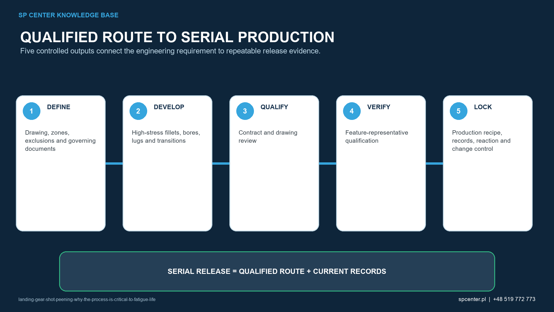
Which events require containment and change review?
- Wrong drawing, repair instruction, specification revision or approved source was used.
- Required inspection before peening was missing or indicated damage.
- Coverage was not demonstrated in a bore, fillet or behind a masking boundary.
- Machine, media, fixture, program or treatment map differed from the approved configuration.
- Plating, heat-treatment, grinding or repair sequence changed.
- Traceability to part, batch, media or acceptance records was lost.
Contain affected parts back to the last known acceptable state and obtain the required technical or customer disposition. Additional exposure is not an automatic repair: cumulative peening can affect roughness, dimensions, cold work and residual stress.
How should a landing-gear RFQ be structured?
Provide part number and revision, serial or lot logic, material and heat-treatment condition, incoming surface and prior repair state, treatment and masking map, governing specifications, intensity and strip designation, coverage method, surface and dimensional limits, coating sequence, source-approval requirements, quantity and release records.
For repair work, include the approved repair scheme and design-authority decisions. SP Center can review feasibility and missing inputs, but cannot replace the component authority or invent an acceptance route from incomplete documents.
Frequently asked questions
Why is shot peening used on landing gear?
When invoked by the design or repair authority, controlled peening can introduce beneficial compressive residual stress in fatigue- or stress-corrosion-sensitive surfaces. The required zones and acceptance evidence remain component-specific.
Which landing-gear parts can be shot peened?
Examples include drawing-defined regions of cylinders, axles, pins, torque links, lugs, bores, fillets and transitions. This is not a universal list; the controlled drawing or repair data determines each part.
Can shot peening repair a crack or grinding burn?
No. Peening is not a crack or grinding-damage repair. Required inspection and disposition must establish an acceptable incoming surface before the approved peening route proceeds.
Does landing-gear work always require Nadcap?
Only when the customer or contract invokes it. Nadcap accreditation covers an audited supplier scope; it is separate from customer source approval, part qualification and batch release.
Does correct Almen intensity prove a bore is acceptable?
No. Intensity verifies the standardized stream at its defined location. Bore access and coverage, surface condition, dimensions and any other invoked component checks remain separate.
Can a generic aerospace peening recipe be used?
No. Material, heat treatment, geometry, treatment map, coating or repair sequence, governing specifications and customer approvals must define or qualify the route.
Can a landing-gear part be peened again after plating removal or repair?
Only through an approved repair or rework route. Prior exposure, material removal, surface condition, dimensions and the new coating sequence require technical review and renewed acceptance evidence.
What should be sent for quotation?
Send the controlled drawing or approved repair data, part and material condition, treatment and exclusion zones, invoked specifications, intensity and coverage, coating sequence, quantity, source-approval requirements and required release records.
Key takeaways
- Landing-gear peening follows controlled design or repair data, not a generic aerospace recipe.
- Existing cracks, grinding damage or unauthorised material removal require disposition before peening.
- Feature access, Almen intensity and component coverage are separate questions.
- Manufacturing, coating and repair sequence are part of qualification.
- Nadcap accreditation, customer source approval, part approval and batch release are distinct.
- Rework and repeated exposure require explicit authority and renewed evidence.
Related SP Center guides
Technical references
1. SAE AMS2430U: Shot Peening, revised April 2018
2. SAE ARP7488: Peening Design and Process Control Guidelines, issued January 2018
3. SAE J442_202602: Tools for Peening Intensity Determination and Verification, revised February 2026
4. SAE J443_202512: Procedures for Determining and Verifying Peening Intensity, revised December 2025
5. SAE J2277_202301: Shot Peening Coverage Determination, revised January 2023
6. Performance Review Institute, Nadcap
Standards note: Use the complete revisions invoked by the controlled component data and customer contract. Public summaries do not establish a landing-gear repair or acceptance route.
Author: Paweł Kmieć
Discuss a landing-gear requirement: +48 519 772 773 | [email protected]