


How to control beam and fillet treatment, precision bores, split faces, threads, masking, coverage, dimensions and serial evidence
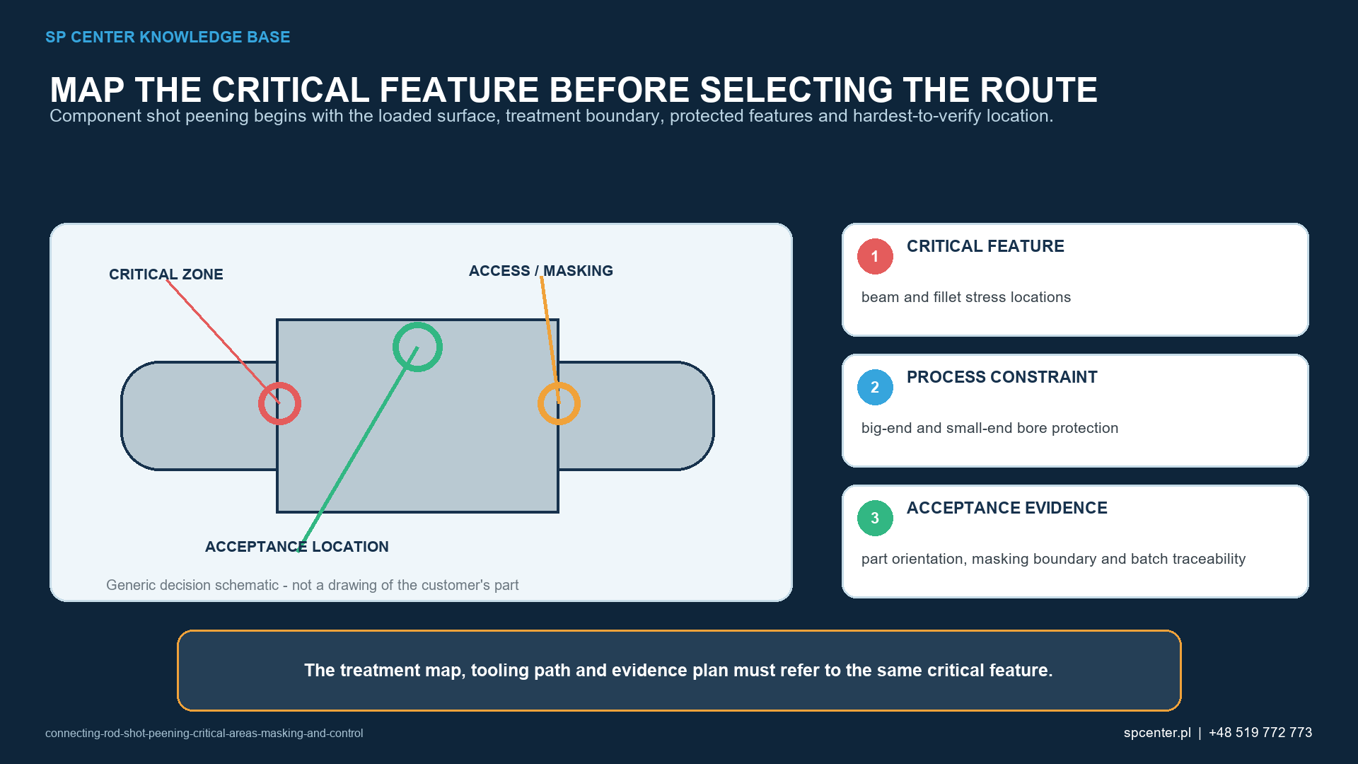
Connecting-rod shot peening is typically developed around drawing-defined beam surfaces and fatigue-critical transitions near the big and small ends. The route must preserve precision bores, split faces, threads, bolt and oil holes, identification and other excluded features. Reliable production combines exact material and manufacturing condition, treatment boundaries, media, Almen intensity, coverage, fixture and masking, dimensional acceptance, traceability and controlled response to interruptions or change.
Why are connecting rods demanding shot peening parts?
A connecting rod carries repeated tensile, compressive, bending and inertial loads through a geometry that combines two bores with a beam and several transitions. Local surface condition, forging flow, machining marks, fillets and notches can influence crack initiation. At the same time, bearing and joint features require tight dimensions, finish and cleanliness.
There is no universal connecting-rod recipe. Forged steel, powder-metal, aluminum, titanium or another construction and condition can require different media, intensity, surface and contamination limits. The exact part number, drawing and material route govern.
Which features need separate controls?
| Connecting-rod feature | Typical concern | Control question |
|---|---|---|
| Beam or shank surface | Fatigue demand, prior forging or machining texture and complete exposure | Which faces are treated and how is circumferential access achieved? |
| Big-end transition and fillet | High local stress, shadowing and boundary near bearing or split features | Can the full radius be reached and inspected without impacting excluded surfaces? |
| Small-end transition | Stress concentration near a precision bore and thin local section | How are bore, edge and transition separately defined and protected? |
| Big- and small-end bores | Bearing fit, size, roundness, surface finish and media retention | Are the bores treated, transitioned or fully excluded by drawing? |
| Split faces, serrations or fracture-split surfaces | Fit, alignment and controlled mating condition | What protection and cleanliness criteria preserve the joint? |
| Bolt holes, threads, oil holes and markings | Dimensional change, trapped media, notch damage or lost identification | Which features are masked, plugged, cleaned and verified? |
Table 1. Treatment benefit and functional risk meet at the transitions beside precision features.
How should treatment boundaries be defined?
The controlled drawing should mark treated, excluded and transition zones. Resolve whether the beam is treated around its full circumference, where the big- and small-end fillet boundaries stop, and how they meet bore chamfers, split faces, bolt bosses, oil holes and markings.
Do not infer the boundary from an old rod, a photograph or a similar engine family. If a general note conflicts with detailed dimensions, repair data or customer specification, place the affected work on hold and obtain formal clarification.
How should bores, faces and threads be protected?
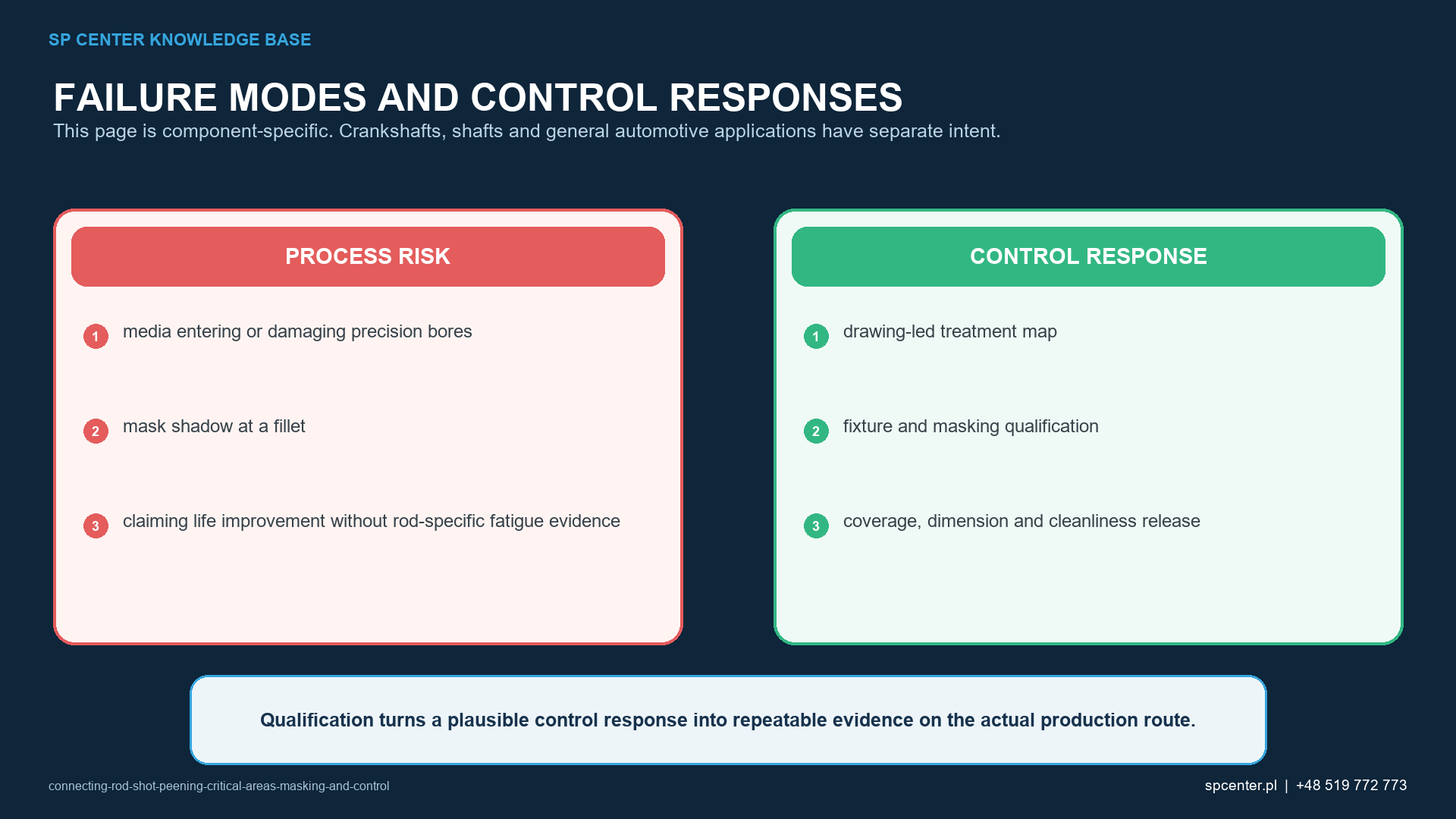
Protection depends on the drawing. Precision bores can be sensitive to roughness, size, roundness and embedded media. Split faces, serrations and fracture-split surfaces rely on their mating condition. Threads, bolt holes and small oil passages can trap media or suffer local notch damage.
Qualify mask or plug material, fit, overlap, durability, identification, installation and removal. A hard mask can cause rebound; a lifted plug can leak media; excessive protection can leave a required fillet untreated. Boundary inspection and cleanliness are part of the route.
How do fixture and part motion affect coverage?
The fixture should locate the rod on controlled datums without damaging critical surfaces. Orientation, clamp force, support, rotation or indexing and nozzle or wheel paths must reproduce access to beam faces and fillets. If multiple parts are processed together, qualify spacing and first-to-last position.
A fixture that is dimensionally similar but changes shadowing, rebound or mask position can change the result. Treat fixture identity, wear limits and replacement as controlled configuration features.
How should Almen intensity and media be selected?
The design or specification authority should define the complete Almen range and strip designation or explicitly authorize a supplier proposal. Selection considers material and heat treatment, section thickness, fillet geometry, incoming surface, media restrictions, roughness and distortion risk.
Pressure, wheel speed, media flow and exposure are process inputs, not substitutes for Almen intensity. Media type, size, hardness, shape, cleanliness and working condition remain separate qualified variables. A conforming Almen result with the wrong or degraded medium is not an equivalent route.
How is complete coverage demonstrated?
Coverage is the degree to which every specified connecting-rod surface shows impact evidence under the approved method. Complete coverage means no visible unpeened area remains within the required zone under the defined inspection conditions. Inspect both sides of each transition, the beam circumference where required and the boundaries next to masks.
Lighting, magnification, surface finish and part orientation should be controlled. A fluorescent or other indirect method requires approval, qualification and correlation. Additional exposure does not repair a shadowed fillet and can overprocess adjacent open areas.
Which manufacturing sequence is appropriate?
The authorized route can place peening before or after particular machining, honing, cleaning, customer-specified inspections outside SP Center's service scope, coating or assembly operations. Later material removal can remove the treated layer; later heat can relax residual stress. A bore may intentionally receive final finishing after adjacent surfaces are peened, but the drawing and process plan must define the sequence.
Incoming forging laps, cracks, decarburization, heat-treatment damage, grinding burn or corrosion require evaluation before peening. The impact texture must not conceal an unresolved condition.
How are dimensions and distortion controlled?
Unbalanced treatment can influence straightness or twist, particularly on light or asymmetric designs. Masks and plugs can affect local contact or leave residues. Depending on the drawing, post-process checks can include big- and small-end bore size and roundness, centre distance, parallelism, straightness, split-face condition, mass or balance and visual damage.
A part with complete coverage but failed dimensions or cleanliness is not conforming. Process adjustment after a dimensional issue must follow qualification and change control.
What evidence belongs to development?
| Development stage | Required output | Evidence boundary |
|---|---|---|
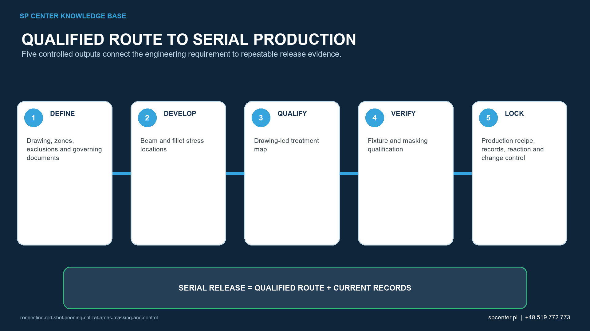
| Requirement review | Current drawing, material and condition, process hierarchy, treatment map, exclusions and proposal authority | No machine settings are selected before technical conflicts are closed |
| Feasibility and fixture | Access, datum, support, loading orientation, masks, plugs, rebound and media-removal plan | The production presentation must represent every critical feature |
| Stream qualification | Media, complete Almen range and strip designation, equipment, holder arrangement and monitored inputs | Almen verifies the stream and not connecting-rod coverage or fatigue life |
| Coverage qualification | Actual or representative geometry, motion, exposure route, boundaries and approved inspection method | Complete coverage is proved on every required zone |
| Part acceptance | Surface damage, roughness, bore and joint cleanliness, dimensions, roundness, distortion and retained media when invoked | A conforming coverage result does not waive functional criteria |
| Part validation | Residual stress, fatigue or other customer evidence only when required | Validation remains within the exact material, geometry and process basis |
Table 2. Stream, coverage, surface, dimensions and component validation answer different questions.
What should be controlled in every batch?
| Batch control | Record to retain | Stop condition |
|---|---|---|
| Part identity and incoming state | Part number, revision, lot, material condition, prior operations, inspection and repair status | Unknown condition, open defect or unapproved repair |
| Configuration | Machine, programme, fixture, mask or plug identity, orientation and operator | Wrong, worn or damaged protection or uncontrolled programme |
| Media and intensity | Media identity and condition plus required Almen evidence | Nonconforming media or failed intensity verification |
| Execution | Cycle, motion, monitored inputs, interruption, alarm and reprocessing status | Exposure cannot be reconstructed or a limit is exceeded |
| Post-process acceptance | Coverage, boundary, damage, cleanliness, dimensions and retained-media checks | Untreated zone, mask leakage, distortion, blocked feature or missing inspection |
| Release | Deviation and disposition status, customer forms, certificate and authorized approval | Open nonconformance, incomplete evidence or unauthorized change |
Table 3. Serial release links the actual rod and lot to one approved configuration and complete evidence set.
How should re-peening and interruptions be handled?
After an alarm, stopped motion, media-feed loss or power interruption, preserve which surfaces were exposed and the part status. Continue, restart or reprocess only under the approved reaction and disposition route. An extra full pass can increase roughness, distortion or local damage.
Machining or repair after peening changes layer depth and geometry. Re-peening requires explicit authority, review of prior exposure and remaining section, and any repeated qualification, coverage, dimensional and inspection evidence.
Frequently asked questions
Which areas of a connecting rod are commonly shot peened?
Drawing-defined beam surfaces and fillets around the big and small ends are common candidates. Precision bores, split faces, threads, bolt holes, oil holes and identification can be treated, transitioned or protected only as specified.
Should the big-end and small-end bores be masked?
Only the drawing and qualified route decide. Bearing or bushing bores often have critical size, roundness and finish and may require protection, but a universal masking rule is not valid.
Can shot peening correct forging laps or cracks?
No. It must not be used to hide forging laps, cracks, decarburization, overheating, grinding damage or unacceptable corrosion. Incoming defects require inspection and authorized disposition first.
Does Almen intensity prove the rod fillets are fully treated?
No. Almen evidence verifies the peening stream under the test arrangement. Coverage must be accepted on the actual specified fillets and beam zones with the approved method.
Can shot peening change connecting-rod dimensions?
Yes. Local plastic deformation, unbalanced exposure, masks and retained media can affect dimensions or function. Bore size and roundness, split-face condition, mass, straightness or other drawing features may require checks.
Can a connecting rod be peened again after machining or repair?
Only through an authorized re-peening or repair route that considers previous exposure, remaining geometry, defect removal, treatment boundaries, qualification and inspections. Do not add an extra cycle informally.
Is PPAP or FAI always required?
No. PPAP, FAI, first-off or customer-source inspection applies only when the contract or customer system invokes it. The scope and approval authority must be defined before production.
What information is needed for a quotation?
Provide the current drawing and revision, material and manufacturing condition, marked treatment and exclusion zones, intensity and coverage requirements, media restrictions, dimensions, lot pattern, qualification, inspections, records, packaging and target date.
Key takeaways
- Define beam, fillet, bore, joint, thread and hole status on the drawing.
- Qualify the exact material and manufacturing condition.
- Treat masks, plugs, fixture and motion as controlled process configuration.
- Keep Almen intensity separate from coverage and functional acceptance.
- Verify dimensions, cleanliness and retained media where invoked.
- Do not hide defects or improvise re-peening after repair or interruption.
Related SP Center guides
Technical references
1. SAE AMS2430U: Shot Peening, revised April 2018
2. SAE ARP7488: Peening Design and Process Control Guidelines, issued January 2018
3. SAE J442_202602: Tools for Peening Intensity Determination and Verification, revised February 2026
4. SAE J443_202512: Procedures for Determining and Verifying Peening Intensity, revised December 2025
5. SAE J2277_202301: Shot Peening Coverage Determination, revised January 2023
Standards note: The complete revisions, drawing and customer-specific requirements invoked by the contract govern.
Author: Paweł Kmieć
Discuss a connecting-rod requirement: +48 519 772 773 | [email protected]