


Match treatment zones to the governing failure mechanism, prove stream access to the complete root and protect flanks, edges, bores and gear microgeometry
Gear shot peening is a feature-specific surface-enhancement process, not a universal instruction to treat the entire gear. When tooth-root bending fatigue governs, the drawing may target the root fillet and adjacent transition. Pitting, micropitting, scuffing and tooth flank fracture involve different locations and mechanisms, so root peening alone does not establish their performance. A defensible route combines design authority, material and case condition, access, intensity, coverage, surface integrity and gear-specific validation.
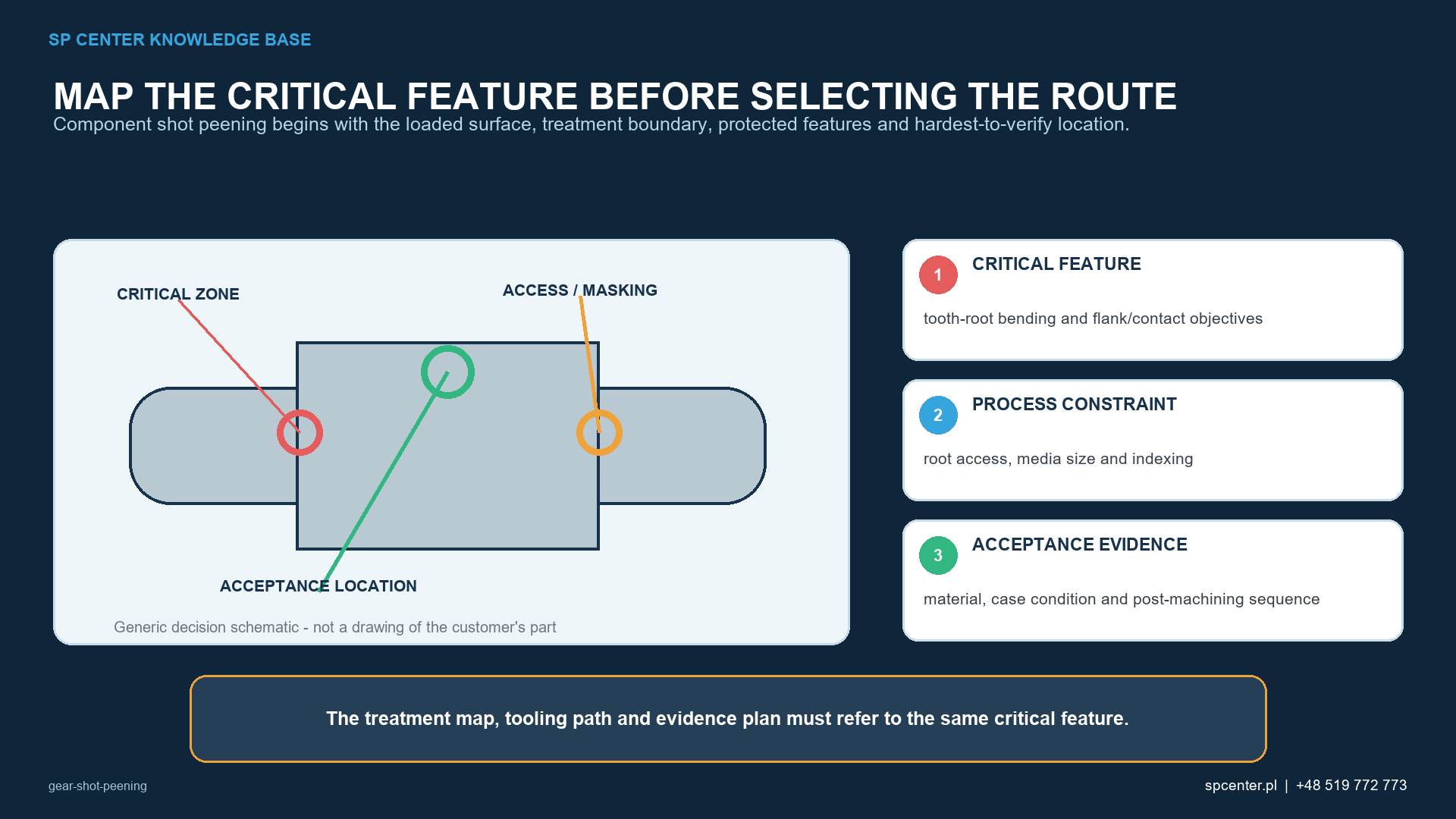
Which gear failure mechanism is being addressed?
| Gear failure mechanism | Primary region | Shot-peening implication |
|---|---|---|
| Tooth-root bending fatigue | Root fillet and adjacent transition | A root-focused treatment can be relevant when the drawing and design basis invoke it |
| Pitting or micropitting | Loaded flank contact | Root peening alone does not establish flank surface durability; finish, lubrication, microgeometry and material state remain central |
| Scuffing or wear | Sliding-contact region | Shot peening is not a substitute for lubrication, tribological design or the required flank finish |
| Tooth flank fracture | Subsurface region below the active flank | Requires separate load-capacity, material and residual-stress assessment |
| Fretting or fatigue at spline/root transitions | Spline flanks, roots or run-outs | Treatment map and evidence must follow the actual spline geometry and failure location |
Table 1. Treatment scope follows the governing failure mechanism and controlled design basis.
During torque transmission, a tooth experiences cyclic bending and contact loading. Root geometry creates a local stress concentration, but crack origin also depends on material cleanliness, inclusions, case condition, machining, residual stress and load spectrum. Not every gear failure starts at the root.
ISO 6336-3 addresses tooth bending strength and ISO 6336-2 surface durability (pitting) within their stated scopes. They are gear-rating standards, not shot-peening process specifications. The drawing or governing process document must separately invoke the peening requirements.
Which tooth and gear features need separate decisions?
| Feature | Access or damage risk | Control question |
|---|---|---|
| Root fillet on both sides of the tooth | Shadowing by adjacent flanks and changing impact angle | Does the qualified stream reach the entire drawing-defined fillet and transition without an untreated band? |
| Loaded tooth flank | Roughness, microgeometry and contact-function sensitivity | Is the flank treated, protected or excluded, and are the invoked finish and profile limits verified? |
| Tooth tip and edge | Rounding, erosion, chipping or local overexposure | Are edge condition and topography protected within a feature-specific window? |
| Bore, spline, datum and mounting face | Media ingress, dimensional change, contamination or loss of fit | Do drawing and mask plan define treatment boundaries and post-process acceptance? |
| Internal gear or narrow tooth space | Restricted line of sight, rebound and media retention | Can the selected equipment and media reach, clean and inspect the actual geometry? |
| Mask boundary or transition zone | Leakage, abrupt treatment edge and ambiguous coverage | Is the boundary located, repeatable and inspected by the approved method? |
Table 2. A gear is a map of functional surfaces and access conditions, not one uniform peening area.
Why is root access difficult?
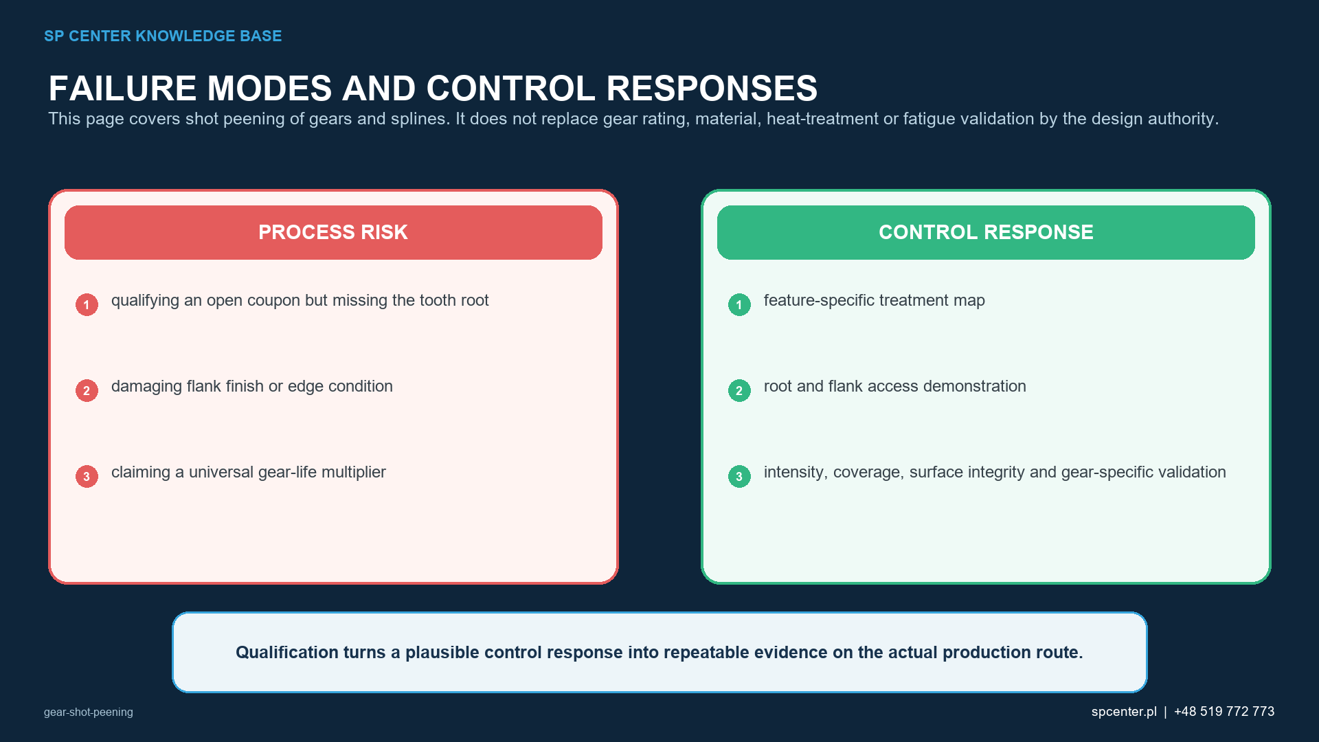
Adjacent teeth restrict line of sight and change the impact angle as the stream crosses the root. Helix, pressure angle, module, root radius, tooth width and internal or external geometry all affect access. A convenient Almen location or open coupon does not prove particle impact at the least accessible root.
Develop the route on the actual or authorized representative gear. Control nozzle or wheel-stream position, stand-off, angle, media mass flow, rotation, indexing, traverse and overlap. Challenge both sides of the narrowest or most shielded root, path start/stop and mask boundary.
How do media and equipment affect a gear route?
Media must fit the root geometry and operating process without violating surface requirements. Size, hardness, material, shape and operating mix influence access, impact and damage. Smaller media can improve access but do not automatically provide the required intensity or profile; larger media can be blocked or damage sensitive features.
Air-blast equipment can provide localized directional access, while wheel systems deliver media through different stream geometry and controls. Neither is universally superior or interchangeable. Qualify the equipment, fixture and motion for the exact gear and requirement.
Why do material and manufacturing sequence matter?
Identify steel grade, material cleanliness, heat-treatment route, hardness and case condition. Carburized, nitrided, induction-hardened and through-hardened gears can have different gradients, retained microstructure, surface sensitivity and contamination limits. Qualification must use the actual or demonstrably representative condition.
Define the sequence relative to grinding, honing, superfinishing, deburring, coating and cleaning. Grinding after peening can remove part of the affected layer. Peening after finish grinding can change root or flank topography and requires the invoked grinding-burn, surface, microgeometry and dimensional controls.
What do intensity, coverage and gear inspection prove?
| Evidence layer | Gear-specific output | What it does not prove alone |
|---|---|---|
| Process verification | Qualified equipment, media, saturation/intensity, mass flow, distance/angle, fixture, rotation/indexing, path and exposure | Complete root coverage, acceptable flank finish or fatigue life |
| Component surface acceptance | Coverage at every specified root/transition, mask boundaries, surface condition, cleanliness and required dimensions | Residual-stress depth profile or bending-strength increase |
| Component validation | Representative root-bending, contact, residual-stress or other invoked evidence for material, case and geometry | Transfer to another gear family or routine stream conformity |
| Traceability and change control | Gear identity, drawing, material/heat treatment, process program, media lot/condition, inspections, deviations and release | Technical performance without the supporting qualification |
Table 3. Stream verification, surface acceptance, component validation and traceability answer different questions.
The objective is a qualified process window, not maximum intensity or exposure. Correct Almen intensity does not prove access; full-looking coverage does not prove the required intensity; and both can coexist with unacceptable roughness, a folded edge, retained media or dimensional nonconformance.
How is coverage assessed at the tooth root?
Evaluate every drawing-defined root surface and transition using the approved direct or qualified indirect method. Lighting, magnification, surface condition and access must be capable of resolving the required decision. A tracer or fluorescent method requires qualification and correlation for the actual root geometry and condition.
Do not infer the hidden side of a root from an exposed witness surface unless the governing method explicitly accepts a representative correlation. Record the inspected locations, method, sampling or full-area rule and acceptance authority.
What surface and dimensional risks remain?
Inspect for cracks, sharp impressions, folds, edge damage, erosion, contamination and retained media as invoked. Verify root and flank roughness, tooth profile/lead, runout, bore, datum or other dimensions only where the drawing or qualification requires them. A compliant average roughness does not cancel a local defect.
If flanks or bores are excluded, masks and plugs become controlled tooling with defined material, fit, life, inspection and removal. Mask leakage or an ambiguous transition requires containment and authorized disposition.
What does a complete qualification close?
| Qualification stage | Required output | Gear-specific challenge |
|---|---|---|
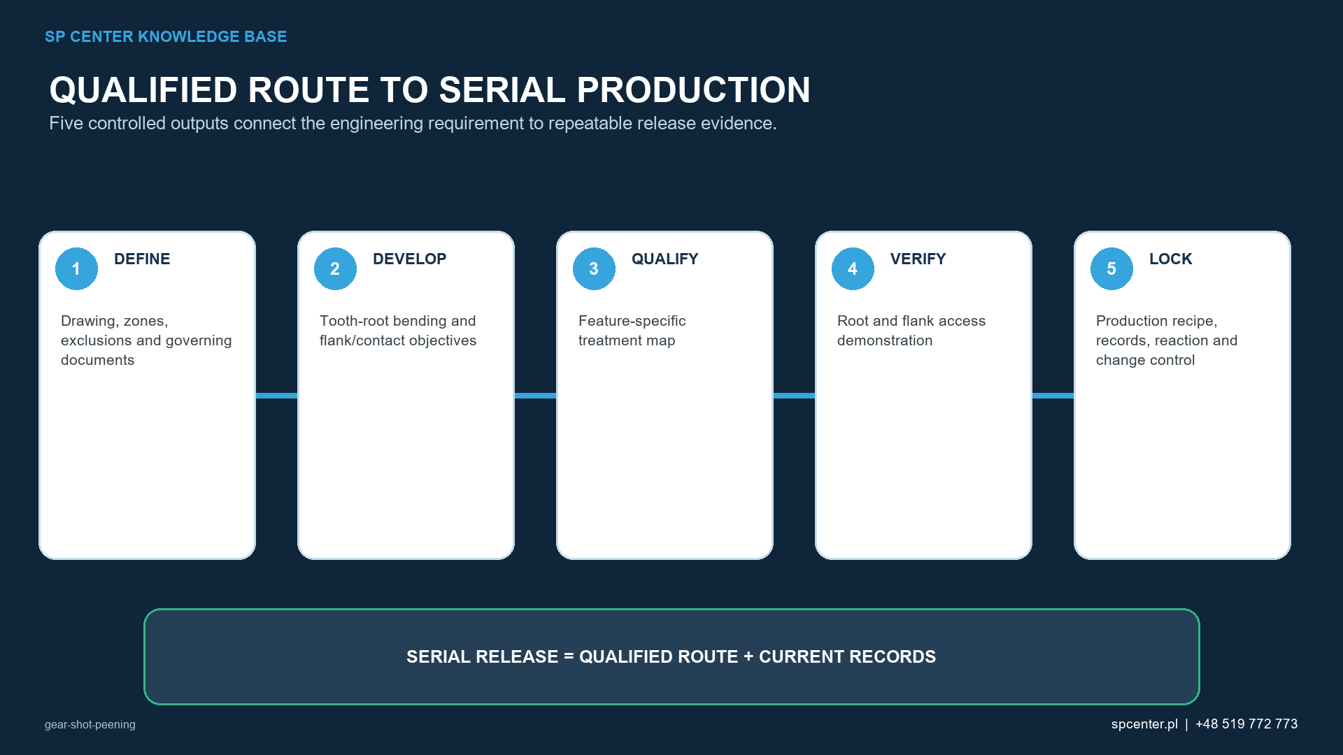
| Requirements review | Controlled drawing, failure mode, material/case, treatment and exclusion map, applicable specifications | Avoid assuming that all teeth or flanks require the same treatment |
| Access development | Representative gear, fixture, mask, nozzle/wheel position, media, rotation/indexing and worst-root challenge | Demonstrate both sides of the least accessible root and all transitions |
| Process window | Valid intensity basis, media and equipment limits, motion, overlap, exposure and alarms | Prevent pressure/time from replacing qualified stream and feature evidence |
| Component acceptance | Coverage, surface, roughness/finish, damage, cleanliness and dimensional results as invoked | Protect functional flanks, edges, bores and datums |
| Performance qualification | Representative test and acceptance criteria where a load-capacity claim is required | Separate bending, pitting, scuffing and flank-fracture questions |
| Serial release | Current configuration, records, reaction plan, authorized deviations and change/requalification triggers | Prevent silent transfer between gear families or machines |
Table 4. Each stage closes a different gear-specific risk before serial release.
What belongs in the production record?
- Gear identity, drawing revision, material, heat treatment, case and incoming finish.
- Treatment, transition, mask and exclusion map for roots, flanks, tips, bores and datums.
- Qualified equipment, media, fixture, mask, nozzle/wheel position, rotation/indexing and program revision.
- Valid saturation/intensity and media-condition records plus monitored process variables and alarms.
- Feature-specific coverage, surface, cleanliness and dimensional acceptance.
- Performance evidence where invoked and its material/geometry/load basis.
- Changes, nonconformances, authorized reprocessing, customer approvals and final release traceability.
Why is the gear tooth root often shot peened?
For gears governed by tooth-root bending fatigue, the root fillet can be a high-stress crack-initiation region. A drawing-authorized peening route may introduce a controlled near-surface state there, but the benefit must be qualified for the actual material and geometry.
Should the entire gear be shot peened?
Not as a universal rule. Root, flanks, tips, bores, splines and datum faces can have different functions and limits. The drawing-defined treatment, transition and exclusion zones control the scope.
Can gear shot peening improve pitting resistance?
A pitting claim cannot be inferred from root peening. Flank contact performance also depends on material, case, hardness gradient, microgeometry, finish, lubrication, load and residual stress. Use a design basis or representative flank validation.
Does correct Almen intensity prove tooth-root coverage?
No. Almen intensity verifies a standardized stream response. Access and impact-impression coverage on both sides of every specified root and transition require separate evidence.
Which gear materials can be shot peened?
Carburized, nitrided, induction-hardened, through-hardened and other gear conditions can require different media, energy, contamination and damage limits. Use the exact alloy, heat treatment, case and incoming surface in qualification.
Should shot peening occur before or after gear grinding?
The sequence follows the drawing and qualification. Grinding after peening can remove the affected layer; peening after grinding can alter finish and requires control of grinding burn, surface condition and flank/root requirements.
Can one gear process be transferred to another module or tooth form?
Not automatically. Tooth spacing, helix, root radius, internal/external geometry, material, case, fixture, access and inspection can change the qualified relationship.
Does shot peening guarantee a specific gear-life increase?
No. Any life or load-capacity credit requires a defined failure mode, representative gear or test geometry, material cleanliness, manufacturing route, load spectrum and acceptance basis.
Key takeaways
- Identify the governing gear failure mechanism before selecting the treatment area.
- For bending-fatigue applications, the drawing-defined root fillet may be the primary target.
- Demonstrate access and coverage at both sides of the least accessible root.
- Control material/case condition and the complete grinding, finishing and coating sequence.
- Keep Almen intensity, coverage, surface acceptance and gear validation separate.
- Make life or load-capacity claims only within a tested or approved design basis.
Related SP Center guides
- Crankshaft Shot Peening
- Shot Peening of Steel Components
- Shot Peening Coverage
- Shot Peening Process Window
Technical sources
3. SAE AMS2430U: Shot Peening, revised April 2018
4. SAE ARP7488: Peening Design and Process Control Guidelines, issued January 2018
5. SAE J2277_202301: Shot Peening Coverage Determination, revised January 2023
Standards note: ISO 6336-2 and -3 remain current rating standards in the official ISO catalogue; they do not replace the invoked shot-peening process specification or customer requirements.
Author: Paweł Kmieć
Discuss a controlled gear shot-peening requirement: +48 519 772 773 | [email protected]