


Choose bulk hardness or a microhardness profile, control cross-section preparation, force, spacing and uncertainty, and avoid confusing hardness with residual stress
Bulk hardness and microhardness answer different questions after shot peening. Rockwell or another macrohardness method can verify the base material or heat-treatment condition, but its indentation usually samples far deeper than the peened surface layer. A Vickers or Knoop microindentation traverse on a prepared cross-section can map a near-surface gradient when the indent size, force, spacing, edge distance and preparation are suitable. Neither method directly measures compressive residual stress or fatigue performance.
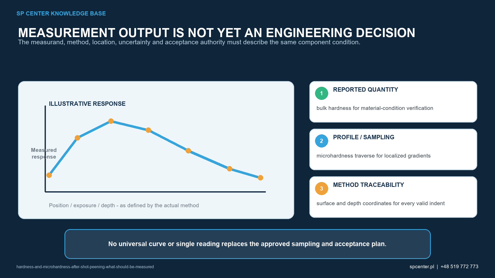
What should the hardness measurement prove?
| Engineering question | Suitable evidence | Main limitation |
|---|---|---|
| Did the base heat treatment meet its requirement? | Approved bulk hardness method at drawing-defined locations | Averages a much larger volume than the peened layer |
| Is there a near-surface hardness gradient? | Vickers or Knoop cross-sectional traverse with selected force and spacing | Preparation, indentation size and edge effects can dominate close to the surface |
| Did peening change one phase or constituent? | Microindentation or instrumented indentation targeted to a documented microstructural region | A single indent cannot represent heterogeneous material |
| Is the component residual-stress profile acceptable? | XRD or another validated residual-stress method when invoked | Hardness is not a residual-stress measurement |
| Will fatigue performance improve? | Representative fatigue or component validation when invoked | Hardness alone does not predict crack initiation or life |
Table 1. Method selection starts with the engineering claim, not with whichever tester is available.
Why can bulk hardness remain unchanged?
Shot peening plastically affects a surface layer whose depth is small relative to many macrohardness indentations. A large indentation integrates the response of the surface and underlying material, so the result can be dominated by the base heat treatment. That is not evidence that the surface was untreated.
Bulk hardness remains important when the drawing requires a material condition before or after peening. Use the prescribed scale, location, thickness and surface preparation. Do not move the test onto a rough treatment zone merely to make it sensitive to peening.
How is a microhardness depth profile prepared?
Section the article or a technically approved representative coupon at the defined location and orientation. Mount and prepare the cross-section while retaining the true edge and avoiding excessive rounding, heating, smearing or preparation-induced cold work. Identify the original peened surface after preparation.
Place indents at documented depths along one or more traverses. The selected force must produce measurable, valid indents while resolving the gradient. Indents must meet the spacing and edge-distance rules of the governing method and remain within the intended constituent.
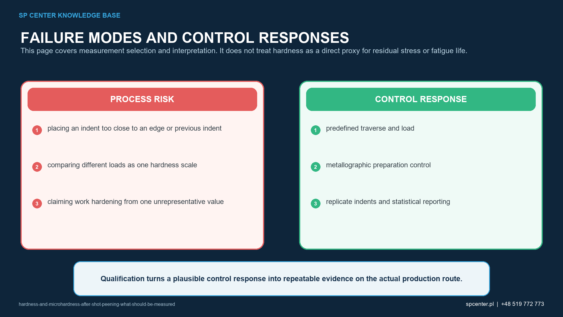
Which measurement details must be controlled?
| Measurement variable | What must be reported | Risk if omitted |
|---|---|---|
| Method and indenter | Vickers, Knoop, Rockwell or instrumented method and full standard revision | Values from different scales are treated as directly equivalent |
| Test force and dwell | Applied force, dwell and loading protocol | Indentation-size effect or load dependence is hidden |
| Preparation | Section orientation, mounting, grinding and polishing route, edge retention and final surface quality | Rounding or preparation deformation moves or changes the gradient |
| Location | Distance from the original surface, traverse direction, feature and coordinate reference | Profiles are shifted or taken from non-equivalent zones |
| Spacing and geometry | Indent separation, edge distance, diagonal or depth and validity rules | Neighbouring plastic zones or free edge affect the result |
| Sampling and uncertainty | Number of traverses, indents per depth, scatter, calibration and uncertainty | One favourable indent is reported as the component response |
Table 2. A hardness number without method, force, location and uncertainty is not a reproducible profile.
How should the first near-surface point be interpreted?
The point closest to the edge is also the most vulnerable to rounding, lost material, roughness, a poorly defined surface coordinate and free-edge influence. A smaller indent can improve spatial resolution but can increase sensitivity to tip geometry, optical resolution and individual microstructural features.
Predefine the minimum valid distance and how the surface coordinate is established. Do not extrapolate a single high value to zero depth or discard a low value merely because it conflicts with the expected mechanism.
What is the difference between Vickers, Knoop and instrumented indentation?
Vickers uses a square-based diamond pyramid and reports hardness from measured diagonals. Knoop produces an elongated shallower indentation that can be useful where the available layer or spacing is limited. The suitable choice depends on the full method, force, material and geometry.
Instrumented indentation derives hardness and other parameters from force and penetration depth. ISO 14577-1:2026 notes that internal stress, pile-up, sink-in and other deviations from ideal behaviour add uncertainty. Results must not be treated as automatically interchangeable with optical HV or HK values.
Can hardness quantify cold work?
A hardness gradient can support evidence of near-surface work hardening, but it is affected by microstructure, prior treatment, indentation size and residual stress. It does not uniquely quantify plastic strain or XRD peak broadening. Define the intended correlation on the actual material and method.
Similarly, a constant hardness profile does not prove the absence of compressive residual stress. Use each measurement for the quantity it can validly address.

How should unexpected results be investigated?
| Observation | Possible explanation | Required check before conclusion |
|---|---|---|
| No change in bulk hardness | Peened layer is shallow relative to the macroindentation volume | Use a justified cross-sectional method if a gradient is the question |
| High value at the first indent | True work hardening, edge effect, roughness reference error or preparation deformation | Repeat valid traverses, inspect the indent and verify surface reference |
| Large scatter near surface | Texture, heterogeneous microstructure, indent too large or too close to edge | Review preparation, force, spacing, constituent and measurement capability |
| Different HV at different force | Indentation-size effect, microstructure or optical uncertainty | Do not merge forces; report and compare like-for-like |
| Higher hardness but poor fatigue | Roughness, damage, inclusions, residual-stress relaxation or wrong failure mechanism | Review fractography, surface and residual-stress evidence |
| Profile differs from witness coupon | Material, geometry, exposure, section or preparation is not representative | Reconfirm equivalence and traceability to the processed part |
Table 3. The measurement system and sample preparation are checked before a process conclusion is drawn.
How are hardness results linked to the shot peening route?
Record part and lot, material and heat treatment, exact measurement location, machine, media, Almen intensity, coverage, fixture, masks, exposure, process sequence and time to sectioning where relevant. A witness is useful only when its material, orientation, surface and exposure represent the claim.
For change studies, use matched untreated and peened material and the same preparation, indenter, force and traverse plan. Report individual values and scatter rather than only a smoothed curve.
Frequently asked questions
Does shot peening always increase hardness?
No. A near-surface work-hardening response can occur, but its magnitude depends on material, initial condition and process. Bulk hardness can remain effectively unchanged because it samples a larger volume.
Can Rockwell hardness measure the peened layer?
Usually not when the affected layer is shallow relative to the indentation. Rockwell can still verify bulk heat-treatment hardness when specified at an appropriate location.
Should microhardness be measured directly on the peened surface?
A rough, curved or dimpled surface can make optical indentation measurement unreliable. A carefully prepared cross-section is often more suitable for a depth profile, subject to the governing method.
Is Vickers or Knoop better near the surface?
Neither is universally better. Indenter geometry, force, layer depth, microstructure, edge distance and measurement uncertainty determine suitability. The selected method must be qualified for the intended resolution.
Can hardness be converted between HV, HK and HRC?
Conversions are approximate and material-dependent and can be especially misleading for gradients, cold-worked layers and low-force measurements. Report the measured scale and conditions.
Does microhardness prove compressive residual stress?
No. Hardness and residual stress are different quantities. Residual stress can also influence indentation response, so interpret hardness with a separate validated stress measurement when needed.
How many traverses are required?
The plan should reflect microstructural variability, part zones, expected gradient, destructive sampling and required uncertainty. One universal number is not defensible.
Must hardness be checked in every shot peening batch?
Only when the drawing, specification, control plan or customer requirement invokes it. Intensity, coverage and media controls do not automatically create a serial hardness requirement.
Key takeaways
- Bulk hardness verifies a different material volume from microhardness.
- A near-surface gradient normally needs a controlled cross-sectional traverse.
- Method, force, dwell, spacing, edge distance and preparation must be reported.
- The first surface-adjacent indent carries the greatest measurement risk.
- Hardness, residual stress, cold work and fatigue are related but distinct quantities.
- Use only the serial hardness requirement actually invoked by controlled documents.
Related SP Center guides
- What Shot Peening Does to a Metal Surface
- Residual-Stress Depth Profiles
- XRD Residual-Stress Measurement
Technical references
1. ISO 6507-1:2023, Vickers Hardness Test – Test Method
2. ASTM E384-22, Microindentation Hardness of Materials
3. ASTM E92-23, Vickers and Knoop Hardness of Metallic Materials
4. ISO 14577-1:2026, Instrumented Indentation Test
5. SAE ARP7488: Peening Design and Process Control Guidelines, issued January 2018
Standards note: Use the complete test-method and product requirements invoked by the drawing, plan or contract.
Author: Paweł Kmieć
Discuss a surface-integrity requirement: +48 519 772 773 | [email protected]