


Control wear in media delivery, recovery, motion and monitoring, then verify maintenance against the qualified shot peening baseline
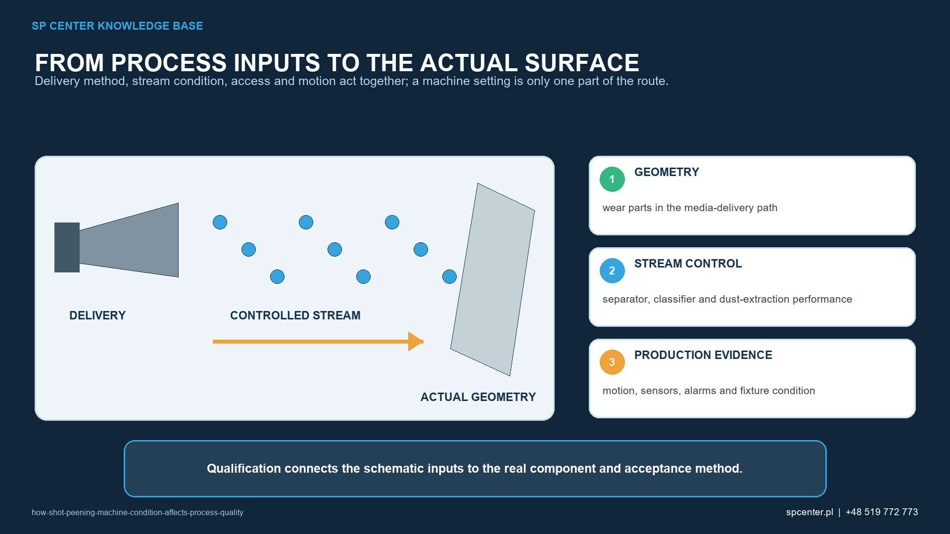
Shot peening machine condition affects the physical stream that reaches the component. Worn nozzles, wheel parts, hoses, metering devices, separators, sensors or fixtures can change impact energy, media flow, footprint, access or exposure while the stored recipe still looks correct. Maintenance therefore belongs to process control: its limits, records and post-maintenance checks must be tied to the qualified equipment and part geometry.
Which machine conditions can change shot peening quality?
| Equipment function | Condition to control | Possible process effect |
|---|---|---|
| Pneumatic delivery | Nozzle bore and profile, hose, fittings, regulator, metering device and media mass flow | Velocity, flow, footprint and local intensity can shift |
| Wheel delivery | Wheel speed, blades, impeller, control cage, liners and feed | Throw pattern, media velocity and distribution can shift |
| Media recovery | Separator or classifier settings, screens, magnets and contamination removal | Operating mix can gain fines, oversize particles, fragments or foreign material |
| Dust extraction | Airflow, differential pressure, ducts, seals and collection condition | Fines removal, visibility, housekeeping and equipment stability can deteriorate |
| Part handling | Fixture datums, clamps, backlash, robot or axis motion and program revision | Access, angle, stand-off, exposure time and overlap can change |
| Monitoring | Sensors, interlocks, alarms, calibration or verification and data capture | A physical change may not be detected or linked to the affected batch |
Table 1. Condition monitoring follows each function that creates, delivers, recovers, directs or records the media stream.
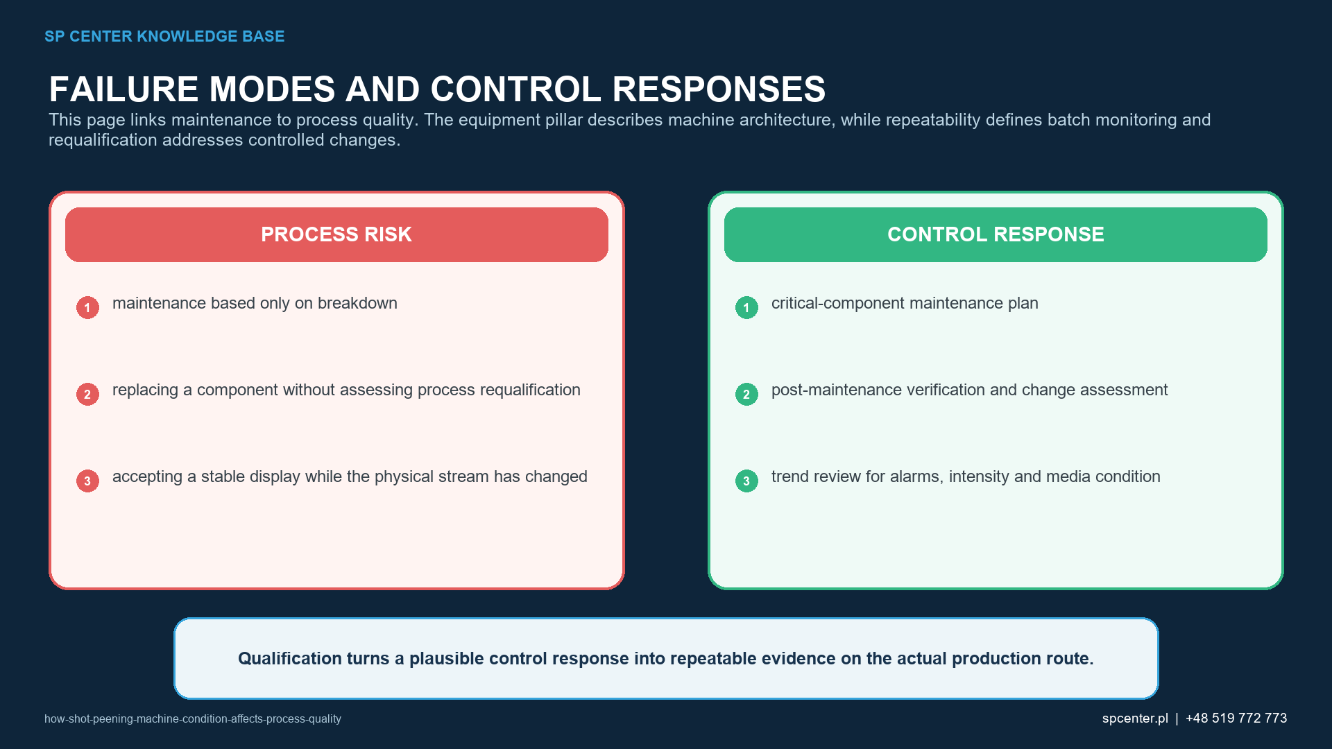
The listed effects are coupled. A worn nozzle may change flow and footprint; a classifier problem may change the operating mix; fixture backlash may move the part out of the qualified stream. A stable display value is therefore an instruction or indication, not complete evidence of the physical condition at the component.
How does pneumatic equipment wear affect the process?
In a pneumatic system, the nozzle bore and internal profile can erode. The resulting change can alter air-media acceleration, media mass flow and the shape of the impact footprint. Hoses, bends, fittings, seals, regulators and media-metering devices can restrict, leak, pulse or disturb delivery.
Record the nozzle type and approved dimensional or performance limit. Inspect the complete path rather than the nozzle alone. Pressure, airflow and media mass flow describe different quantities, and none should be used as a standalone substitute for Almen intensity or component coverage.
How does wheel equipment wear affect the process?
Wheel speed, blade condition, impeller, control cage, liners and media feed influence media velocity and throw pattern. Wear or incorrect assembly can shift the high-energy zone or broaden the distribution. A current or speed display can remain stable while the physical pattern changes.
Wheel-process verification therefore includes the parts and settings that determine media exit and the component’s position relative to the pattern. Pneumatic and wheel peening are not automatically interchangeable; each route needs its own qualified baseline and maintenance response.
Why do separator, classifier and dust-extraction condition matter?
The recovery system should retain the qualified operating media mix and remove rejected particles and foreign material according to the approved route. Screens, classifiers, separators and magnets can lose effectiveness or be set incorrectly. The result may be excessive fines, fragments, oversize particles or contamination.
Dust-extraction airflow and filter differential pressure also require controlled limits where they affect fines removal or machine operation. A dust collector is not a substitute for media inspection. Sieve analysis, shape inspection, contamination controls and other invoked checks remain separate evidence.
How can fixtures and motion create hidden drift?
Fixture datum wear, loose clamps, spindle runout, robot or axis backlash, incorrect stand-off, changed angle, program revision or skipped index can alter the treated path. The defect may be local and may not appear in an Almen check performed at another position.
Use a defined reference for fixture position, nozzle or wheel relationship, motion speed and sequence. After intervention, verify the actual production program and direction of travel; a generic dry cycle cannot prove the qualified impact pattern on a difficult feature.
What verification is needed after maintenance?
| Maintenance event | Minimum technical review | Verification selected by risk and requirements |
|---|---|---|
| Cleaning or adjustment within an approved instruction | Confirm configuration, settings and inspection result | Documented functional check and any required production check |
| Like-for-like wear-part replacement | Confirm identity, dimensions, installation and effect on the qualified stream | Flow, pressure or speed check; footprint, intensity or coverage check as applicable |
| Nozzle, wheel, metering or motion change | Assess whether energy, distribution, access or exposure can change | Controlled comparison with the approved baseline; requalification when invoked |
| Sensor, software or alarm change | Assess measurement range, logic, revision and record integrity | Verification of signal, interlock, recipe and traceable data capture |
| Repeated alarm, damage or unexplained drift | Contain product since the last known acceptable state and investigate cause | Broader process and product evidence before release |
Table 2. The event is assessed for its possible effect; the applicable contract and approved change procedure determine the final verification scope.
A like-for-like replacement is not automatically process-neutral. Conversely, not every routine action requires full requalification. The technical decision should be documented before production resumes and should identify the last known acceptable state if the event followed a failure.
Which measurements should be trended?
| Trend or check | Useful question | Limit of the evidence |
|---|---|---|
| Nozzle bore, wheel parts and liners | Is wear approaching the approved action limit? | Dimensions alone do not prove the component footprint |
| Air pressure or wheel speed | Is the commanded energy input stable? | Neither variable alone proves Almen intensity |
| Media mass flow and operating mix | Is the delivered media quantity and condition controlled? | A total flow value may hide local distribution |
| Almen intensity and saturation curve | Does the standardized stream meet the invoked intensity requirement? | It does not prove coverage on every component feature |
| Coverage or approved tracer method | Did required surfaces receive the defined impact coverage? | It does not quantify residual-stress depth or fatigue life |
| Fixture and motion check | Is the component presented to the stream as qualified? | A dry run does not prove media impact response |
Table 3. Trends support early detection only when the measurement method, location, frequency, action limit and reaction plan are defined.
Use equipment condition and process results together. For example, nozzle bore trend can trigger planned replacement, while intensity and footprint checks determine whether the qualified output remains valid. Do not create universal limits without equipment-manufacturer data, qualification evidence and the governing requirement.
How should an out-of-condition event be contained?
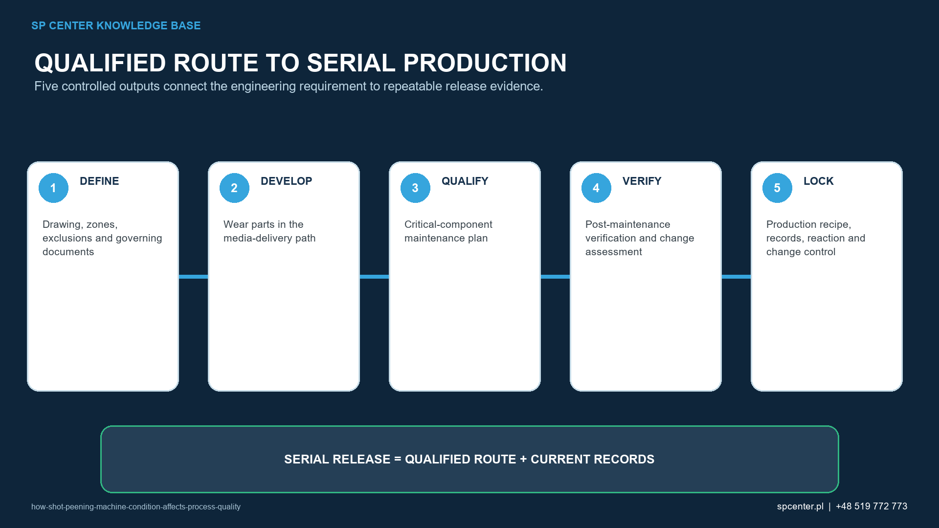
- Stop the affected route and preserve alarms, settings and physical evidence.
- Identify the equipment, program, media, fixture and batches since the last known acceptable state.
- Separate equipment failure, measurement-system error, setup error and product nonconformity.
- Repair through an approved instruction and document replaced parts and configuration.
- Perform the selected post-maintenance verification and obtain the required technical or customer disposition.
- Release product only when batch-specific acceptance remains demonstrated.
Additional exposure is not an automatic correction. Reprocessing can affect roughness, dimensions, surface integrity and cumulative exposure and requires explicit authorization when the controlled requirements allow it.
What belongs in the maintenance control plan?
Define the controlled component, inspection method, frequency, warning and action limits, responsible role, replacement instruction, verification after intervention, record retention and requalification trigger. Link each machine or fixture identifier to its qualified program and part family.
For procurement or transfer, request the equipment configuration and control capability rather than a generic promise of preventive maintenance. A defensible route shows how physical wear is detected before it invalidates intensity, coverage, access or records.
Frequently asked questions
Can a shot peening machine remain in control when its recipe values are unchanged?
Not necessarily. Nozzle or wheel wear, media delivery, separator performance, fixture position, motion and sensor condition can change the physical process while the displayed setpoints remain constant.
Does every wear-part replacement require full requalification?
No universal rule applies. Review whether the change can affect the qualified relationship between settings, stream, geometry and acceptance. The drawing, specification, customer approval and controlled change procedure determine the required verification or requalification.
Is an Almen strip check sufficient after maintenance?
It can verify the standardized intensity condition when performed under the applicable method, but it may not detect a shifted component footprint, access problem, fixture error or coverage failure. Select additional checks from the maintenance risk.
How often should nozzles or wheel parts be replaced?
Use approved inspection and action limits based on equipment design, media, throughput, wear trend and qualified process sensitivity. A universal calendar interval is not technically defensible.
What should be checked after replacing a nozzle?
Confirm nozzle identity, bore and installation, hose and metering condition, air and media delivery, stand-off and orientation. Verify the affected outputs against the approved baseline, including footprint, intensity or coverage where required.
Why does separator condition matter?
It influences the operating media mix by separating reusable particles from fines, fragments, oversize material and contaminants. A changed mix can affect impact consistency and surface condition.
When should product be contained?
Contain potentially affected batches when machine damage, an alarm, failed verification or unexplained drift makes the last acceptable process state uncertain. Release requires a documented technical disposition and the required evidence.
Which machine-condition records should follow the batch?
Keep the records invoked by the control plan: equipment and program identity, media, key settings, inspections, maintenance state, intensity and coverage evidence, alarms, deviations and release authorization, with traceability to the processed lot.
Key takeaways
- Displayed recipe values do not fully describe the physical media stream.
- Pneumatic nozzles and wheel-system wear change the process through different mechanisms.
- Media recovery, fixtures, motion, sensors and data capture are part of machine condition.
- Post-maintenance verification is selected from the possible effect and governing requirements.
- Intensity, footprint, coverage and component evidence answer different questions.
- Potentially affected batches remain contained until the last acceptable state and release basis are established.
Related SP Center guides
- Shot Peening Equipment and Controls
- Shot Peening Repeatability
- Requalification After Machine, Media or Fixture Changes
Technical references
1. SAE ARP7488: Peening Design and Process Control Guidelines, issued January 2018
2. SAE AMS2430U: Shot Peening, revised April 2018
3. SAE AMS2432E: Shot Peening, Computer Monitored, revised October 2022
4. SAE J443_202512: Procedures for Determining and Verifying Peening Intensity, revised December 2025
5. SAE J2277_202301: Shot Peening Coverage Determination, revised January 2023
Standards note: Apply the complete revisions invoked by the drawing, contract and customer flow-down. This guide does not create a universal maintenance interval or requalification rule.
Author: Paweł Kmieć
Discuss a controlled shot peening route: +48 519 772 773 | [email protected]