


Control asymmetric plastic strain, incoming stress, fixture restraint and measurement state before a compliant component leaves its dimensional window
Thin-walled parts can be shot peened successfully, but their usable process window is often narrower than that of stiff components. Near-surface plastic strain and residual stress can bend, twist or locally buckle a compliant section. Distortion control is therefore part of process qualification: it starts with the incoming shape and stress state, continues through treatment design and fixture release, and ends with free-state dimensional and surface acceptance.
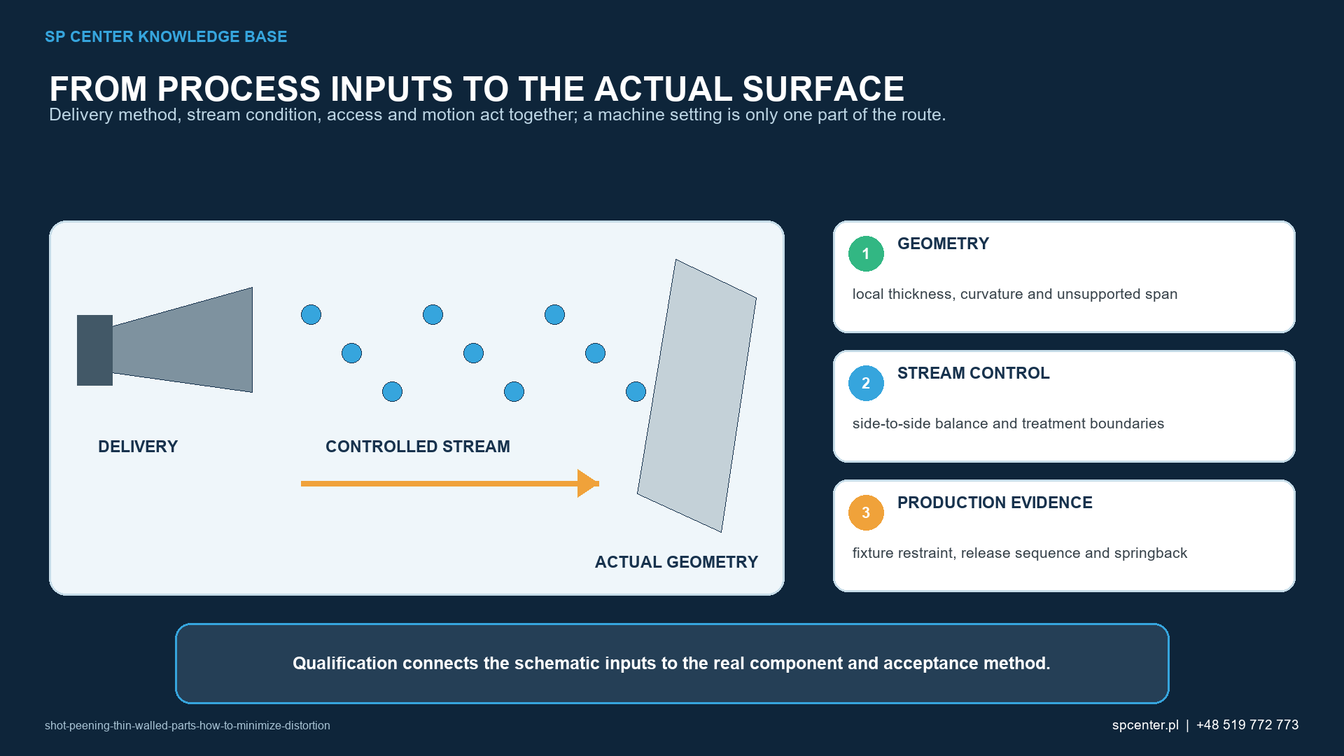
Why does shot peening distort a thin section?
Each impact plastically stretches a small surface region. The underlying material restrains that layer, producing a self-equilibrating residual-stress field. If the affected layer or exposure differs through the thickness or across the surface, the resulting strain mismatch creates curvature or twist.
Thin wall is a structural description, not a fixed thickness. A ribbed panel, blade edge, tube, diaphragm and machined pocket have different stiffness even at the same nominal wall. Local transitions and unsupported spans can dominate the response.
| Risk driver | Why it matters | Data required before trials |
|---|---|---|
| Wall thickness and stiffness | The peened layer occupies a larger fraction of the load-carrying section and has greater leverage on shape | Thickness map, unsupported spans, section transitions, ribs, edges and local curvature |
| One-sided or nonuniform treatment | Differential in-plane plastic strain creates bending, twist or local waviness | Treatment map, access angles, overlap, start/stop zones and opposite-side condition |
| Incoming residual stress | Machining, forming, welding or heat treatment can relax and combine with peening stress | Manufacturing route, stress-relief status and free-state geometry before peening |
| Fixture restraint | A clamp can suppress movement during impact yet store elastic springback or create contact marks | Support and clamp layout, torque or load, repeatability, protected surfaces and release sequence |
| Material and surface | Yield strength, hardening, anisotropy, coating or prior damage change plastic response | Grade, heat treatment, orientation, hardness, initial roughness and defect limits |
Table 1. Distortion risk combines geometry, incoming state, treatment asymmetry and restraint.
What baseline must be established before peening?
Define material, heat treatment, hardness, grain or forming direction, wall-thickness map, critical datums, permissible free-state shape and surface condition. Record machining, forming, welding, straightening and thermal operations that can leave residual stress.
Measure representative parts before peening using the same temperature, support and datum logic planned for the final inspection. If the incoming shape varies significantly, a successful average process may still produce unacceptable tails.
How are parameters selected for a narrow process window?
| Control strategy | Potential value | Qualification caution |
|---|---|---|
| Meet the lowest acceptable qualified intensity | Can reduce plastic-strain magnitude while satisfying the invoked requirement | Do not go below drawing or specification limits; verify the complete saturation curve and part result |
| Select media and impact conditions for access | Can reduce coarse indentation and improve treatment of small features | Smaller media does not automatically mean low damage or adequate depth |
| Balance sides or alternate zones | Can reduce net curvature where geometry and requirements allow | Opposite-side peening changes the stress state and may be prohibited or create new critical surfaces |
| Use repeatable support and progressive sequencing | Limits vibration, oil-canning and local dwell variation | Measure the released part; fixture-constrained shape is not the acceptance condition |
| Control path overlap and start/stop exposure | Reduces local double exposure and untreated bands | Robot path alone does not prove particle exposure or coverage |
| Use simulation and instrumented trials | Helps rank sensitive zones and plan measurements | Model predictions require measured input and free-state dimensional validation |
Table 2. Distortion controls are useful only when they remain inside the authorized treatment requirement.
Intensity remains a process response determined from a valid saturation curve; it is not pressure or wheel speed. Coverage remains a surface-observation requirement. Neither value alone predicts component shape, and a conforming Almen strip does not release a dimensionally nonconforming part.
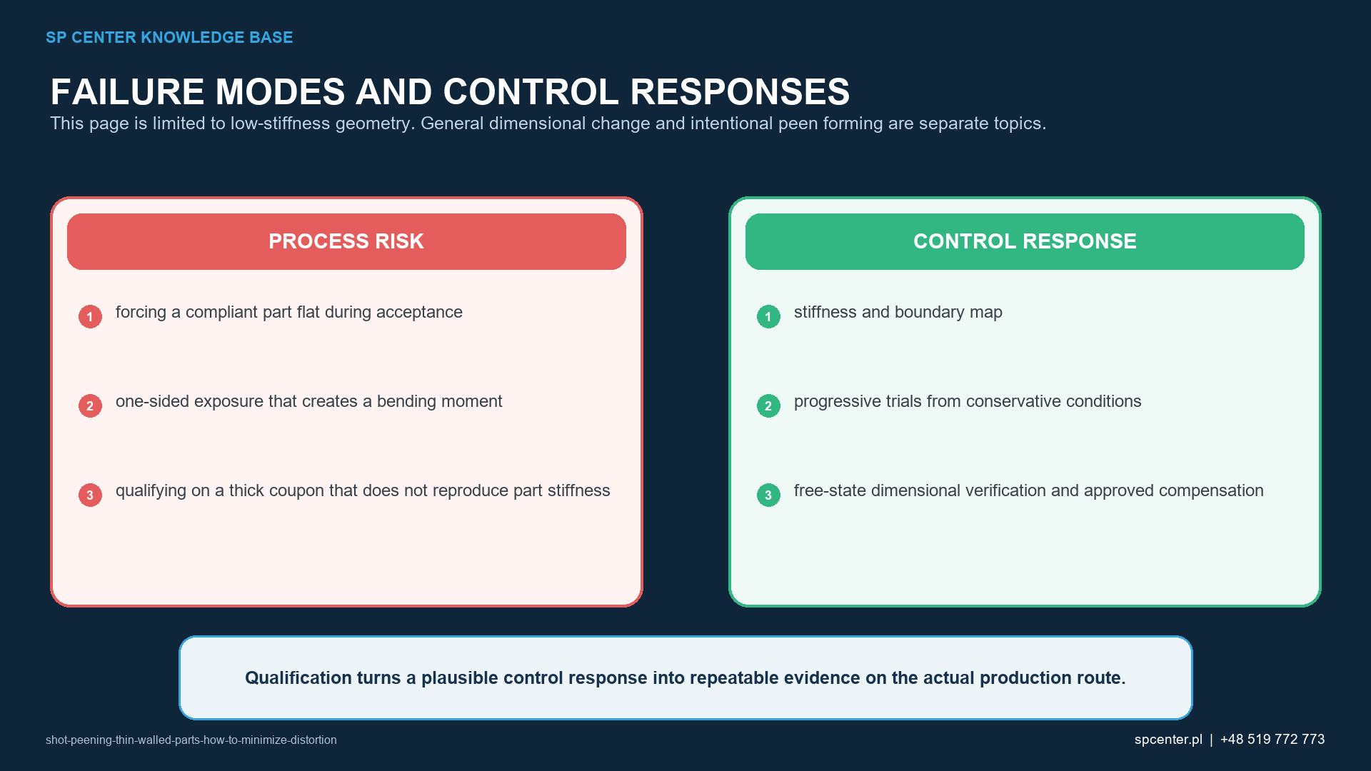
How should fixtures support a thin part?
A fixture should establish repeatable position, resist harmful vibration and avoid excessive shadowing or contact pressure. Support near compliant spans can reduce oil-canning during impact. Clamp surfaces, loads, sequence and wear must be controlled.
Fixture restraint does not remove the underlying strain mismatch. The critical geometry can appear only after unclamping. Qualification therefore documents both the restrained process setup and the released measurement condition.
Can treatment be balanced between surfaces?
Alternating zones or treating opposite surfaces can reduce net curvature in some designs, but it also changes the complete residual-stress field and surface condition. A surface that is functionally critical, coated, inaccessible or explicitly excluded must not be peened as an informal counterbalance.
Where balanced treatment is allowed, qualify side order, time between sides, orientation, exposure, overlap and fixture state. “Equal time” does not prove equal local impact conditions.
Why do start, stop and overlap zones matter?
Robot acceleration, turnarounds, nozzle indexing and manual dwell can create local overexposure. Mask edges and fixture transitions can create sharp treatment gradients. On a compliant wall, these local differences can produce waviness even when the overall part bow is acceptable.
Use an exposure map that includes ramp-in, ramp-out, overlap and repositioning. Confirm it with representative coverage evidence and dimensional mapping rather than the programmed path alone.
How should distortion be measured?
Define pre- and post-process coordinate systems, support points, restraint state, temperature, stabilization time and filtering. Report bow, twist, profile, position and local waviness separately. A fixture-gauge pass may miss free-state springback.
Scanning or dense point measurement is helpful for thin panels, but the data-reduction method and datum fit can hide or exaggerate shape change. Retain raw data and compare the same evaluation method before and after peening.
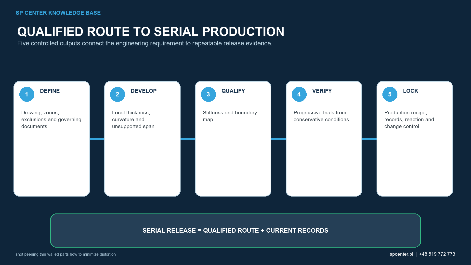
What evidence qualifies the process?
| Qualification output | Method | Acceptance question |
|---|---|---|
| Process intensity | Valid saturation curve and Almen verification with defined holder orientation and stream location | Is the qualified process response inside the required range? |
| Coverage and treatment boundary | Approved direct or qualified indirect method on representative geometry | Are all required surfaces treated without unintended zones? |
| Free-state geometry | Repeatable datum scheme, temperature control and dimensional scan after fixture release and stabilization | Do bow, twist, profile, position and local waviness meet the drawing? |
| Surface integrity | Visual or microscopic inspection, roughness or topography and edge or thin-feature examination | Are indentation, folding, cracking, fretting or contact marks acceptable? |
| Residual stress or performance | Qualified depth measurement, representative fatigue or structural evidence where required | Does distortion control retain the intended functional benefit? |
| Repeatability | Multiple parts across safe parameter and incoming-condition boundaries | Is the process capable, not merely successful once? |
Table 3. Qualification must close both the shot peening requirement and the dimensional-risk claim.
Use several representative parts and boundary conditions rather than a single successful sample. If the process benefit relies on residual-stress depth or fatigue, verify that a distortion-reduction measure such as lower energy or opposite-side treatment has not invalidated that basis.
How is shot peening separated from peen forming?
Shot peening for surface enhancement aims to meet intensity, coverage and component requirements while maintaining drawing geometry. Peen forming intentionally creates a controlled curvature. It requires a forming plan, target contour, springback strategy, measurements and approvals suited to that purpose.
Do not treat unplanned distortion as acceptable forming, and do not correct it by extra peening without an authorized rework route. The additional cold work and residual-stress redistribution can affect durability even when shape is recovered.
What should the control plan retain?
- Incoming free-state dimensions, residual-stress route and part orientation.
- Wall-thickness and stiffness risk map with critical zones.
- Qualified saturation curve, intensity range, media and exposure settings.
- Fixture drawing, supports, clamp loads, wear limits and release sequence.
- Program revision, side order, overlap and transition controls.
- Coverage, surface-integrity and dimensional acceptance methods.
- Post-process free-state data and stabilization conditions.
- Deviation, rework, approval and traceability records.
Frequently asked questions
What thickness counts as thin-walled for shot peening?
There is no universal number. Risk depends on thickness relative to the plastically affected layer, unsupported span, curvature, stiffness, material, incoming stress and treatment asymmetry.
Can a rigid fixture prevent distortion?
It can control movement during peening, but the part may spring back after release and the fixture can introduce contact marks or local shadowing. Acceptance must use the defined free-state condition.
Should both sides be peened to balance distortion?
Only when the drawing, functional surfaces and qualified process allow it. Two-sided treatment changes the residual-stress field and exposure; it is not a universal correction.
Does lower Almen intensity always reduce distortion?
It often reduces the imposed plastic-strain magnitude, but the relation depends on the component and process. The selected value must remain within requirements and be validated on representative parts.
Can Almen arc height predict part distortion?
Not directly. The strip is a standardized process-response tool with its own material and geometry. A component needs a validated correlation or model and direct dimensional evidence.
Is shot peen forming the same as distorted shot peening?
No. Peen forming intentionally uses controlled differential strain to achieve a target shape. Unplanned distortion during surface enhancement is a nonconformity unless an approved forming route says otherwise.
Can a distorted part be re-peened on the opposite side?
Not without an approved disposition and qualified rework plan. Extra exposure changes residual stress, cold work, roughness and fatigue response and may move the part beyond its process limits.
When should dimensions be measured?
Use the approved sequence, normally including a controlled pre-peen baseline and a post-peen free-state measurement after release and defined stabilization. Temperature and support conditions must be consistent.
Key takeaways
- Define thin-wall risk by stiffness and strain imbalance, not thickness alone.
- Measure the incoming and released part in the same controlled free state.
- Use fixtures to stabilize the process, not to hide springback.
- Balance sides only when authorized and fully qualified.
- Control local start, stop, overlap and mask-transition exposure.
- Keep surface enhancement, peen forming and distortion rework as distinct routes.
Related SP Center guides
- Dimensional Change After Shot Peening
- Shot Peening Fixtures
- Shot Peening Process Window
- Shot Peening Simulation
Technical references
1. SAE J2441_202511: Shot Peening, stabilized November 2025
2. SAE ARP7488: Peening Design and Process Control Guidelines, issued January 2018
3. SAE J442_202602: Tools for Peening Intensity Determination and Verification, revised February 2026
4. SAE J443_202512: Procedures for Determining and Verifying Peening Intensity, revised December 2025
5. Finite element analysis of shot peening and flexible-panel distortion, 1998
6. Residual-stress depth profiles in thin shot-peened steel plates, 2001
7. Multiple-impact modelling of residual stress and distortion in thin peened structures, 2012
8. Closed-loop shot peen forming with in-process measurement, 2022
Standards note: Dimensional control does not override the complete intensity, coverage, surface, material, customer or qualification requirements for the part.
Author: Paweł Kmieć
Discuss a distortion-controlled shot peening plan for thin-walled parts: +48 519 772 773 | [email protected]