


Use numerical models to explain impact mechanics, compare controlled scenarios and map residual stress—without replacing required measurements or process qualification
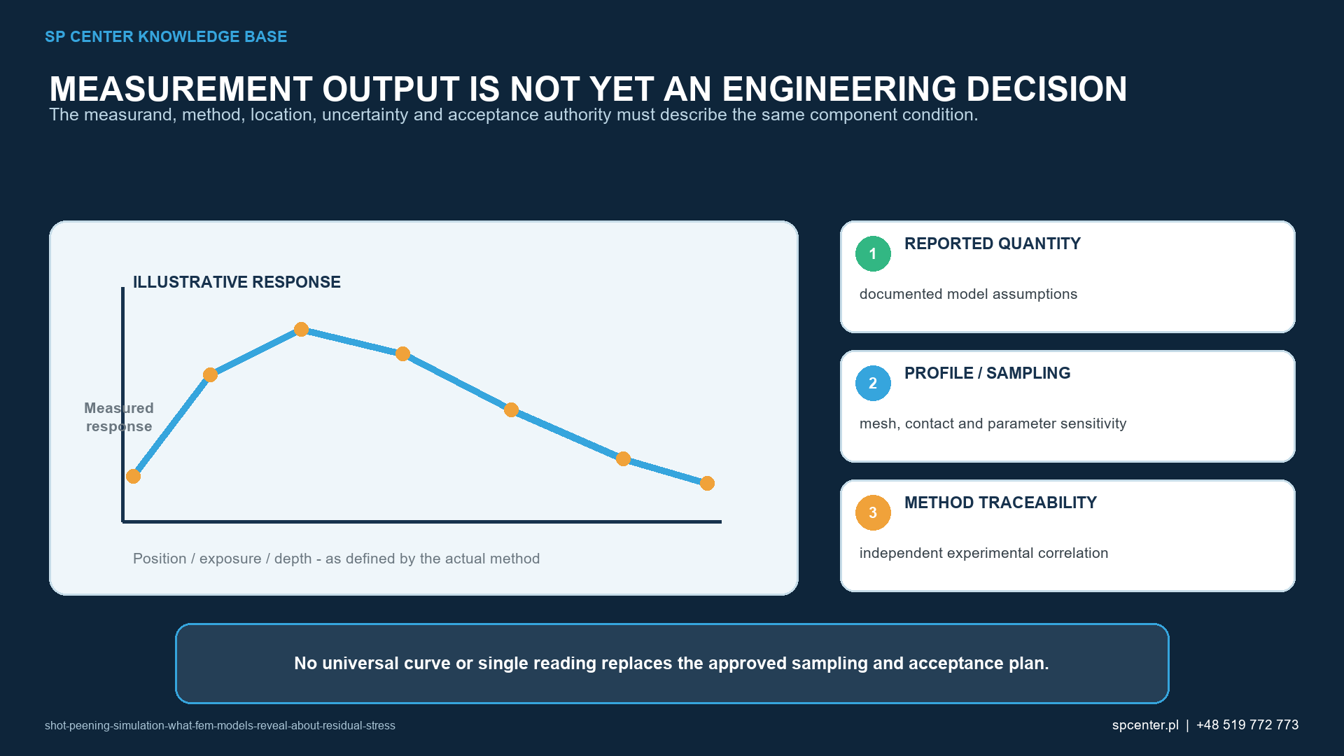
Shot peening simulation can reveal mechanisms that are difficult to measure during impact: local plastic strain, interaction between repeated dimples, residual-stress depth and component distortion. It does not reveal them automatically. The result is conditional on impact inputs, material law, geometry, boundary conditions, numerical choices and validation. A coloured contour is evidence from a model, not proof that the production process or part conforms.
What can a shot peening simulation answer?
A model should begin with a written question and an intended decision. Examples include ranking the influence of velocity and shot size, understanding oblique impact in a bore, comparing impact sequences, estimating a residual-stress field for structural analysis or studying distortion of a thin component.
The required fidelity follows the claim. A single-impact model can explain local mechanics but cannot establish a statistically representative operating mix. A calibrated eigenstrain method can map stress and distortion across a large component but may not resolve a local edge or dimple.
| Modelling approach | Useful question | Main limitations |
|---|---|---|
| Single-impact explicit FEM | How shot diameter, velocity, angle, contact and target constitutive response form a local plastic zone | Does not represent operating-mix statistics, impact interaction or production coverage by itself |
| Multiple-impact FEM | How spacing, order, overlap and repeated plasticity affect an area-averaged residual-stress field | Computational cost, boundary effects and sensitivity to artificial impact pattern |
| DEM-FEM or trajectory-to-FEM coupling | How media transport and component geometry create local velocity and incidence distributions | Requires credible flow, collision and coupling assumptions plus measured process correlation |
| Eigenstrain or imposed-strain mapping | How a calibrated near-surface inelastic strain field drives component stress and distortion | The transferred field is not universal and can miss local contact or defect effects |
| Reduced-order or surrogate model | How to screen a qualified design space or support sensitivity and optimization studies | Reliable only inside the training and validation domain |
Table 1. Different simulation architectures answer different engineering questions and are not interchangeable.
How does explicit impact FEM represent the process?
In an explicit dynamic model, one or more particles contact an elastic-plastic target at defined velocities and angles. The calculation resolves transient stress waves, contact, plastic flow and unloading. Residual stress is evaluated after kinetic effects have decayed and equilibrium has been recovered.
Mesh density must resolve the dimple and stress gradient. The domain and boundaries must avoid artificial reflection or restraint in the region of interest. Energy balance, time-step stability, contact penetration and the stress state after dynamic settling are part of the numerical quality record.
Why do multiple impacts and statistics matter?
Production shot peening contains a distribution of particle sizes, velocities, angles, locations and sequences. Nearby plastic zones interact, while repeated hits can change hardening and surface shape. A regular grid of identical impacts can be useful for a controlled study, but it is not automatically representative of a random stream.
Where stochastic impact locations or a DEM-derived trajectory set is used, document the sampling rule, number of realizations, convergence of area-averaged outputs and seed control. Numerical “coverage” should be defined explicitly, for example by impact density or projected dimple area, and kept separate from production coverage assessed under the governing method.
Which inputs dominate credibility?
| Input family | Evidence expected | Risk if simplified without justification |
|---|---|---|
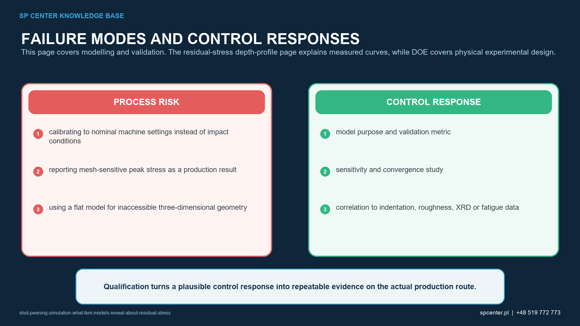
| Impact conditions | Velocity and angle distribution, shot size and shape distribution, local flux or impact density | Nominal air pressure, wheel speed or one average velocity may misrepresent local energy |
| Shot behaviour | Density, elastic-plastic response, restitution or justified rigid-shot assumption, contact properties | Rigid perfect spheres can understate energy loss, fracture, shape and operating-mix effects |
| Target material | Elastic properties, yield and hardening response, strain-rate and cyclic behaviour where relevant, initial state | A quasi-static monotonic curve can produce a plausible but wrong depth profile |
| Geometry and boundary | Representative curvature, thickness, edges, holes, constraints and pre-existing stress state | A flat half-space cannot automatically represent a fillet, bore, thin wall or constrained part |
| Numerics | Mesh and time-step convergence, contact definition, domain size, damping, impact sequence and averaging rule | Numerical artefacts can be mistaken for physical gradients or saturation |
Table 2. Input pedigree matters as much as solver sophistication.
Machine settings are not universal impact conditions. Air pressure, wheel speed and nominal media flow are upstream controls. The model needs the local particle conditions at the surface or a validated relation that derives them. The same nominal setting can produce different impact distributions after nozzle wear, separator drift, media degradation or a geometry change.
How should the material law be selected?
Shot impact involves high local strain, strain rate, unloading and repeated plasticity. Depending on purpose, the law may need strain-rate sensitivity, isotropic and kinematic hardening, cyclic response, thermal coupling or damage. More parameters do not guarantee a better model; each active mechanism needs identifiable data.
Record material grade, heat treatment, hardness, specimen orientation, test temperature, test method and fitting range. Parameters fitted only to quasi-static monotonic data should not be presented as validated for dynamic repeated impact without supporting evidence and sensitivity analysis.
What do residual-stress contours really mean?
Distinguish surface stress, maximum compressive stress, depth of that maximum and depth of the compressive layer. State the coordinate system, tensor component, averaging region and reference state. Nodal peaks beside a contact edge are not equivalent to an area-averaged X-ray measurement.
Residual stress is self-equilibrating. Component thickness, curvature, free edges, machining stress and constraints affect redistribution. A local half-space profile cannot be pasted into a component without a justified mapping method and equilibrium check.
How are calibration and validation separated?
Calibration identifies uncertain parameters using a declared data set. Validation tests the resulting model against independent evidence relevant to the intended claim. Using the same residual-stress profile both to tune velocity or hardening and to claim validation is circular.
Plan withheld process conditions, materials or geometries where feasible. Report measurement uncertainty and modelling uncertainty. A model can be valid for trend ranking within a bounded domain yet unsuitable for absolute acceptance values or a different alloy.
Which measurements should support the model?
| Claim | Corroborating evidence | What does not close the claim alone |
|---|---|---|
| Residual-stress magnitude and depth | Method-qualified X-ray or other suitable depth profile at defined locations, with uncertainty and material-removal effects controlled | Matching surface stress or maximum compression at one point |
| Surface topography or damage | Measured roughness or topography and inspection of representative parts at relevant boundaries | Residual-stress agreement without surface assessment |
| Component distortion | Dimensional or curvature data before and after processing with fixture and initial-state control | Almen arc height transferred directly to a different component |
| Process trend | Independent conditions withheld from calibration and correctly ranked by the model | A fitted result at the calibration condition |
| Fatigue or durability benefit | Representative fatigue, fracture-mechanics or approved design evidence incorporating surface and residual-stress relaxation | A compressive stress contour alone |
| Production acceptance | Drawing, specification, qualified procedure and required process inspections | Simulation output used instead of required Almen, coverage, media or part acceptance |
Table 3. Each model claim needs evidence matched to that output.
Residual-stress depth measurement can require incremental material removal and a correction or interpretation appropriate to the method and geometry. Use a qualified procedure and report location, direction, depth convention, uncertainty and any correction. SAE AS7045 provides a framework for defining and classifying residual-stress measurement; the complete controlled method remains decisive.
How can simulation support process development?
Simulation is valuable for sensitivity ranking, identifying unsafe or uninformative experiments, selecting measurement depths and locations, comparing fixture or access concepts and mapping a validated near-surface field into a distortion or fatigue analysis. It can reduce trial-and-error without eliminating physical trials.
Use a designed study with realistic bounds and interactions. Do not optimize only maximum compressive stress: depth, surface tension, roughness, distortion, damage risk, access and process capability can impose competing constraints.
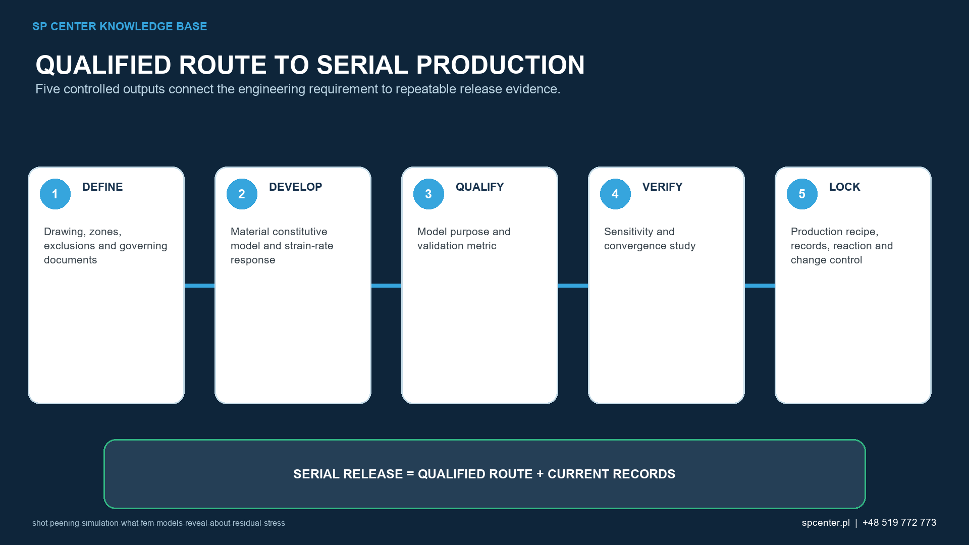
What belongs in a model qualification record?
- Intended use, decision, geometry, material and process domain.
- Software, solver, version, units, model files and revision control.
- Source and uncertainty of impact, media and material inputs.
- Constitutive equations, parameters and calibration evidence.
- Mesh, time-step, domain, contact and boundary sensitivity.
- Impact sequence, randomization, averaging and convergence rules.
- Independent validation data, deviations and acceptance criteria.
- Known limitations, prohibited extrapolations and approval authority.
Frequently asked questions
Can FEM predict the residual-stress profile from shot peening?
It can estimate a profile for the stated model, inputs and domain. The prediction becomes decision-grade only after sensitivity, convergence and independent experimental validation appropriate to the intended use.
Is Almen intensity a direct residual-stress input?
No. Almen intensity is a standardized process response determined from a saturation curve. It can support process correlation, but it is not a universal conversion to impact velocity or component residual stress.
Can nominal air pressure or wheel speed define the impact velocity?
Not reliably by itself. Nozzle or wheel condition, media flow, shot size, transport losses, angle, distance and local geometry influence the velocity and impact distribution.
Does 100% coverage mean every model node receives one impact?
No. Production coverage is an observed surface condition under the applicable method. A numerical impact pattern is a modelling construct and must not be equated automatically with visual coverage.
Which material model is best for shot peening FEM?
There is no universal choice. Select and identify a constitutive law that represents the material, heat treatment, strain-rate range and repeated plasticity needed for the claim, then calibrate and validate it.
Can an eigenstrain field be transferred to any component?
No. Transfer is justified only for the defined material, process, orientation, depth field and geometry assumptions. Curvature, free edges, holes and local access can require new evidence.
Can simulation replace X-ray diffraction or other residual-stress measurement?
Not when measurement is required for qualification or acceptance. Simulation can interpret, interpolate or design experiments, but substitution requires an explicitly approved technical basis.
Does a validated residual-stress model prove fatigue life?
No. Fatigue also depends on roughness, defects, material, geometry, loading, environment, stress redistribution and relaxation. A separate validated life-assessment basis is required.
Key takeaways
- Define the decision and claim before choosing the model.
- Use local impact conditions, not nominal machine settings alone.
- Separate single-impact mechanics from multiple-impact statistics and production coverage.
- Validate the material law, numerical solution and intended output independently.
- Keep simulation, residual-stress measurement and production acceptance as distinct evidence layers.
- Do not extrapolate beyond the validated material, geometry and process domain.
Related SP Center guides
- Residual-Stress Depth Profile After Shot Peening
- Design of Experiments for Shot Peening
- Shot Peening Process Window
- Hardness and Microhardness After Shot Peening
Technical references
2. SAE ARP7488: Peening Design and Process Control Guidelines, issued January 2018
3. SAE J2277_202301: Shot Peening Coverage Determination, revised January 2023
4. Ould et al., finite-element modelling of shot peening, Materials Science and Engineering A, 2006
6. Klemenz et al., FEM prediction and experimental verification of surface-layer characteristics, 2009
7. Guechichi et al., simulation from process parameters to component residual-stress fields, 2016
Standards note: Simulation does not replace complete drawing, specification, customer, measurement or qualification requirements.
Author: Paweł Kmieć
Discuss a shot peening simulation or validation plan: +48 519 772 773 | [email protected]