


Use controlled datums, restraint, stream access, masking and motion so every production part repeats the qualified presentation without shadowing or contact damage
A shot peening fixture is part of the process configuration, not merely a holder. It establishes part position and orientation, reacts to stream and inertial forces, creates or prevents access, carries masking and often provides rotation or indexing. An apparently small change in a clamp, datum, coupling or centreline can change dwell, overlap, coverage and damage risk.
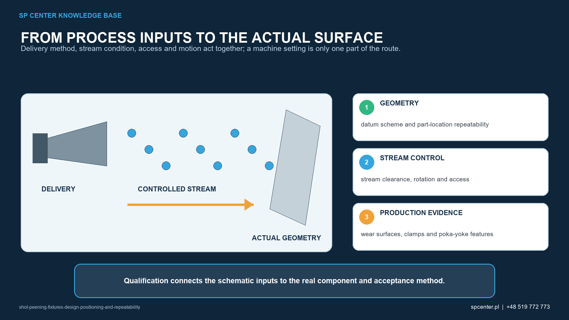
What must a shot peening fixture control?
The fixture must locate the correct part revision in a repeatable coordinate system and keep the treatment zones within the qualified stream envelope. At the same time, it must protect excluded surfaces, avoid scratches and dents and allow loading, cleaning and inspection without hidden media traps.
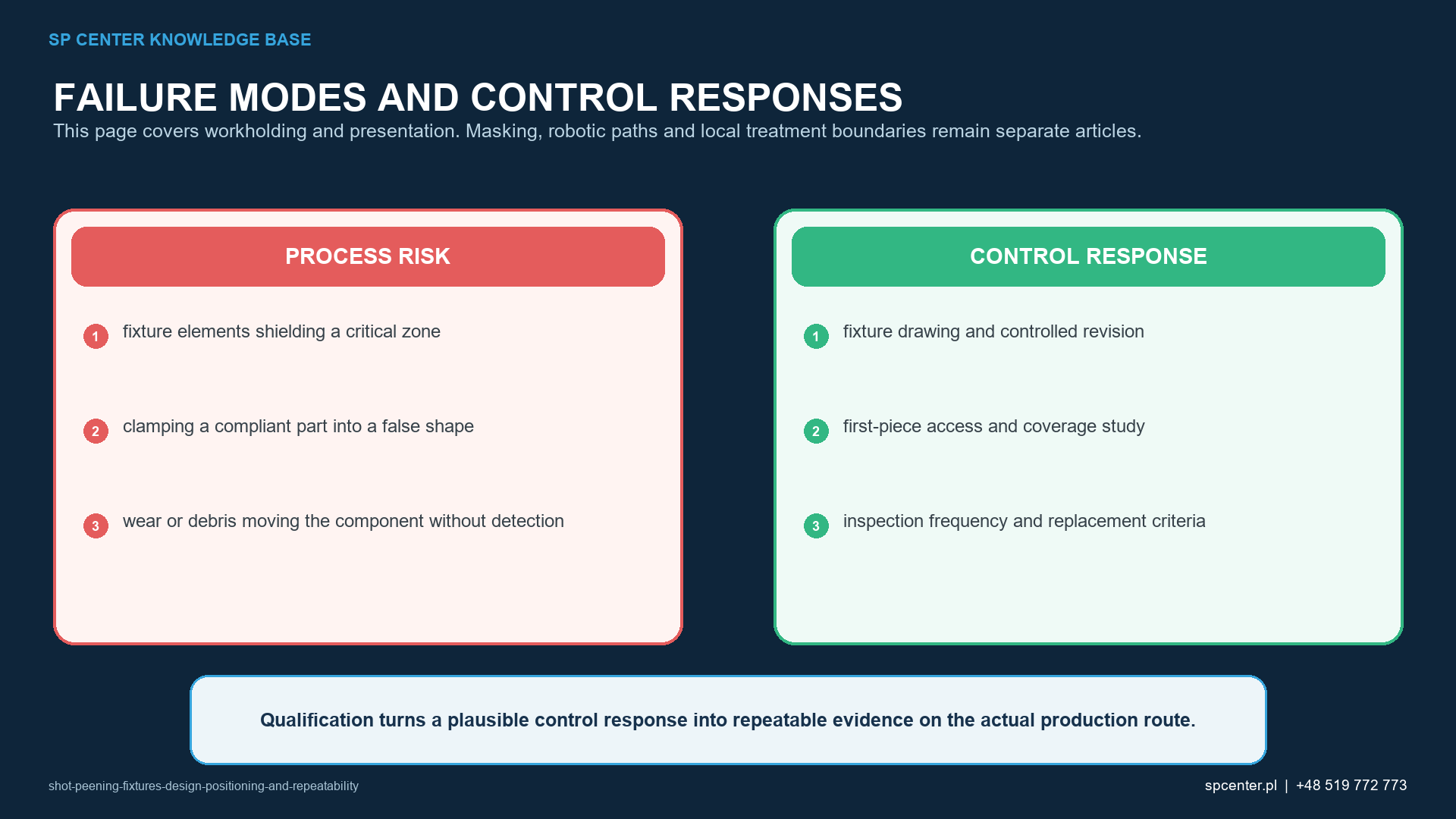
| Fixture function | Failure mode | Design or control response |
|---|---|---|
| Locate the part | Wrong axial, radial or angular position | Use defined datums, positive stops, error-proof orientation and setup verification |
| Hold against stream forces | Movement, vibration or loss of synchronization | Provide adequate restraint without distorting or marking critical surfaces |
| Expose treatment zones | Clamp or body shadows a critical feature | Model and verify the stream envelope; use reorientation or multiple passes where approved |
| Protect exclusion zones | Overspray reaches a fit, seal, thread or precision surface | Integrate qualified masking and verify boundary repeatability |
| Provide controlled motion | Runout, imbalance, slip or backlash changes dwell and overlap | Control centreline, drive interface, speed, phase and condition limits |
| Survive repeated use | Wear, deformation, contamination or media buildup changes presentation | Define cleaning, inspection, maintenance and replacement criteria |
Table 1. Fixture design links part location, access, masking, motion and condition control.
How should datums and orientation be selected?
Use functional or manufacturing datums defined by controlled engineering data where possible. The location scheme should constrain the necessary degrees of freedom without over-constraining a thin or distortion-sensitive part. Positive stops and asymmetric or keyed features can prevent reversed loading.
Setup verification should be simple enough to perform every batch and robust enough to detect the wrong part, revision, spacer, clamp, program or orientation. A photograph can support the work instruction but should not replace measurable or error-proof controls where the risk requires them.
How are shadowing and overspray prevented?
Every clamp, support, drive element and mask occupies part of the stream envelope. The access review should include nozzle or wheel origin, footprint, impact angle, stand-off, part motion and rebound. A clear view in one static position may still become a shadow during rotation or indexing.
If a support contacts a specified treatment zone, the qualified route may require reorientation or multiple positions. The sequence must achieve the required coverage at the former contact area without unacceptable cumulative exposure elsewhere. Moving the clamp informally during production is not a controlled method.
What changes when the fixture rotates or indexes?
Rotating fixtures add centreline, runout, balance, drive torque, slip, backlash, phase and speed controls. Part mass and centre of gravity influence retention and vibration. The fixture must keep the component stable across acceleration, constant speed, reversal and stopping.
Indexing fixtures need unambiguous positions and confirmation that every position was completed. Program and fixture identifiers should prevent a correct part from being run through the wrong motion path.
How are fixture materials and contact surfaces selected?
Fixture material must withstand repeated impacts, cleaning and handling without excessive wear, deformation or incompatible transfer. Contact surfaces should not scratch or indent the component. Coatings, elastomers, tapes and sacrificial inserts require documented compatibility and replacement rules.
Media and debris can collect behind supports or inside drive features. The design should allow inspection and cleaning and avoid releasing trapped media onto a later part. If fixture wear can contaminate a sensitive alloy or lubricant system, the risk must be addressed explicitly.
Which evidence supports fixture qualification and production use?
| Verification layer | Typical evidence | What it does not prove alone |
|---|---|---|
| Design review | Drawing, datum scheme, stream-access and masking review | The built fixture matches the design or remains unworn |
| Fixture acceptance | Identity, dimensions, runout, alignment, balance and functional checks | The complete component coverage under production motion |
| Setup verification | Correct part revision, orientation, clamps, program and tooling | The peening stream meets current intensity requirements |
| Process verification | Almen intensity, saturation and monitored process inputs | The fixture exposes every specified component zone |
| Component inspection | Coverage, damage, masking boundary, dimensions and cleanliness | Future setups will remain identical without fixture controls |
| Maintenance and traceability | Use count, inspection status, repairs, calibration and batch linkage | A design change is technically equivalent without review |
Table 2. Design intent, built condition, setup, process control, component acceptance and maintenance remain separate checks.
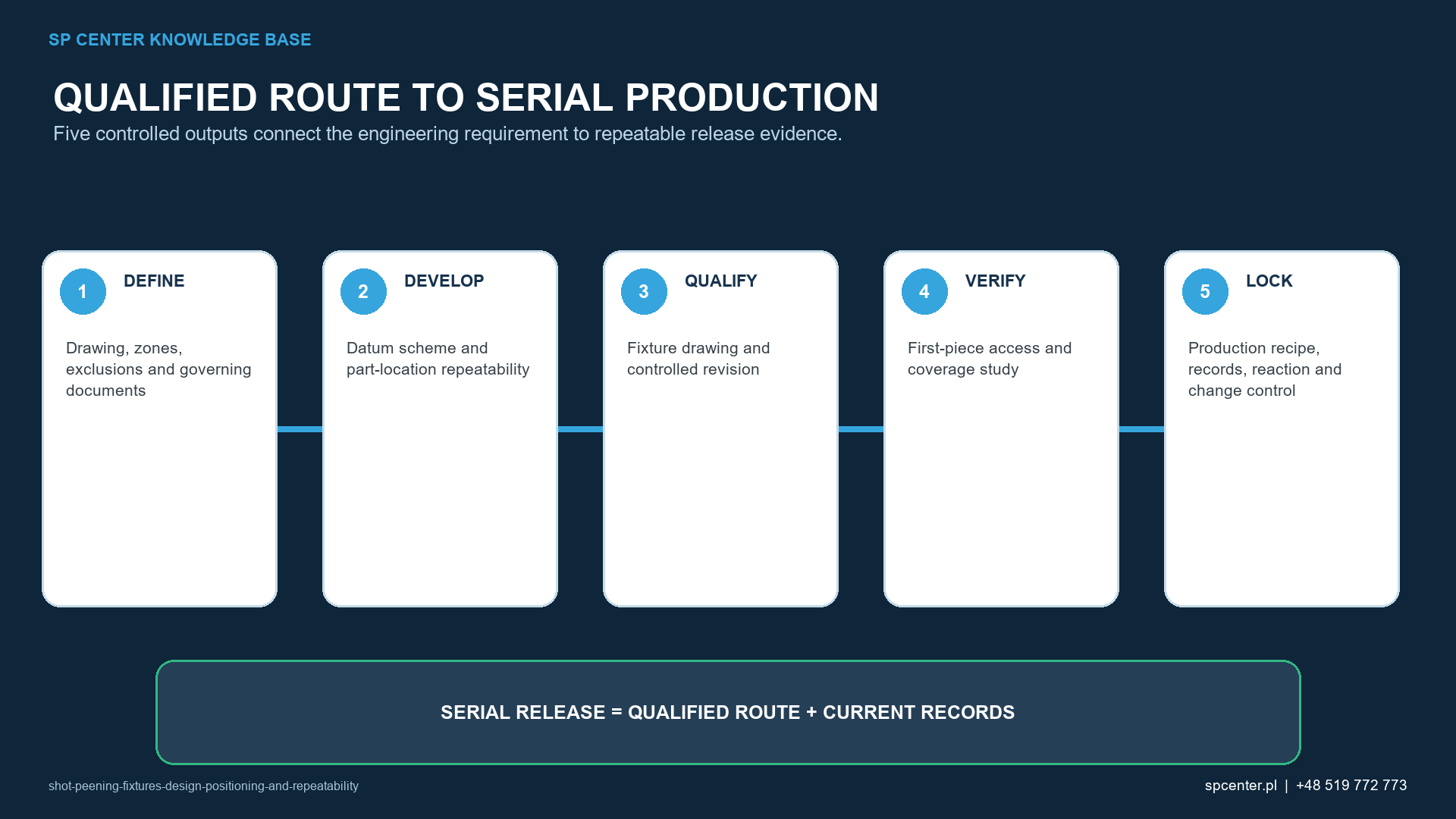
Which changes require review or requalification?
- A datum, locator, clamp, spacer, mask, coupling or drive element changes.
- Fixture material, coating, stiffness or contact insert changes.
- Part mass, geometry, centre of gravity or treatment boundary changes.
- Nozzle, wheel, robot path, stand-off, angle, speed, phase or indexing sequence changes.
- Repair restores geometry by an unapproved method or alters critical dimensions.
- Wear, runout, imbalance, slip, shadowing or recurring coverage variation is found.
Contain affected product from the last verified acceptable fixture state. Preserve the fixture, setup, program and inspection records and assess whether intensity, coverage, surface condition or dimensions may have changed.
What should a fixture design request define?
| Required input | Why it matters | Risk prevented |
|---|---|---|
| Controlled part drawing and revision | Defines datums, zones, tolerances and handling restrictions | Fixture is designed around obsolete or incomplete geometry |
| Part mass, centre of gravity and production orientation | Supports safe drive, balance and retention | Rotation becomes unstable or the part slips |
| Stream source and motion envelope | Defines nozzle or wheel access, stand-off and collision limits | The fixture blocks the qualified stream |
| Treatment, exclusion and transition map | Locates clamps and masking outside critical zones | Contact or overspray damages a functional surface |
| Loading method and cycle quantity | Controls repeatability, ergonomics and wear rate | Manual variation or maintenance interval is ignored |
| Inspection and change authority | Defines acceptance, release, repair and requalification | An undocumented fixture modification enters production |
Table 3. Fixture development needs the actual part, equipment and acceptance envelope, not only a general component name.
Also define identification, storage, handling, cleaning, inspection frequency, maintenance ownership, spare strategy and record retention. A controlled drawing and revision should exist for every production fixture and critical insert.
Frequently asked questions
Is a shot peening fixture part of the qualified process?
Yes. It controls part position, access, motion and masking. A fixture change can alter the qualified relationship and requires documented review.
Can one fixture be used for a family of parts?
Only when the approved family definition and qualification cover the dimensional and functional range, including the worst access, mass, balance and treatment boundary.
Can a clamp touch a surface that must be peened?
Only through an approved multi-position or other qualified route that achieves and verifies the required coverage without damaging the surface.
Does a good Almen result prove the fixture is correct?
No. Intensity verifies the stream in the test arrangement. Fixture positioning, access, motion and component coverage remain separate.
How should fixture wear be controlled?
Identify critical dimensions and surfaces, set inspection and cleaning frequencies, define acceptance and replacement limits, and record repairs or changes.
Can fixture material contaminate the part or media?
Yes. Wear particles, corrosion products, coatings and transferred media can be incompatible. Material and cleaning selection belong in the risk review.
When does a fixture repair require requalification?
When it can change location, access, masking, motion, balance, stiffness, material interaction or any other qualified process relationship.
What information is needed to design a fixture?
Provide the controlled model and drawing, datums, zones, part mass, handling limits, equipment and motion envelope, production quantity and acceptance requirements.
Key takeaways
- Treat the fixture as part of the qualified process configuration.
- Use controlled datums and error-proof orientation for every part revision.
- Verify stream access through the complete motion, not only a static view.
- Control rotating-fixture runout, balance, coupling and slip.
- Define wear, cleaning, repair and replacement limits.
- Keep intensity verification, fixture acceptance and component coverage distinct.
Related SP Center guides
- Localized Shot Peening
- Masking for Shot Peening
- Shot Peening Bores and Internal Surfaces
- Robotic Shot Peening
Technical references
1. SAE J2441_202511: Shot Peening, stabilized November 2025
2. SAE AMS2430U: Shot Peening, revised April 2018
3. SAE AMS2432E: Shot Peening, Computer Monitored, revised October 2022
4. SAE ARP7488: Peening Design and Process Control Guidelines, issued January 2018
5. SAE J442_202602: Tools for Peening Intensity Determination and Verification, revised February 2026
6. SAE J443_202512: Procedures for Determining and Verifying Peening Intensity, revised December 2025
7. SAE J2277_202301: Shot Peening Coverage Determination, revised January 2023
Standards note: Use the complete revisions invoked by the drawing, contract and customer flow-down. The fixture design and its change authority remain application-specific.
Author: Paweł Kmieć
Discuss fixture development for a shot peening project: +48 519 772 773 | [email protected]