


Protect drawing-defined functional surfaces while preserving coverage beside the boundary and controlling shadowing, rebound, leakage and tool wear
A shot peening mask defines where the qualified mechanical process may act and where it must stop. It must protect the specified no-peen area while preserving stream access and required coverage immediately beside the boundary. Masking is therefore controlled process tooling: design, material, fit, installation, wear limits and post-process inspection are qualified with the component, media, intensity, delivery geometry and motion.
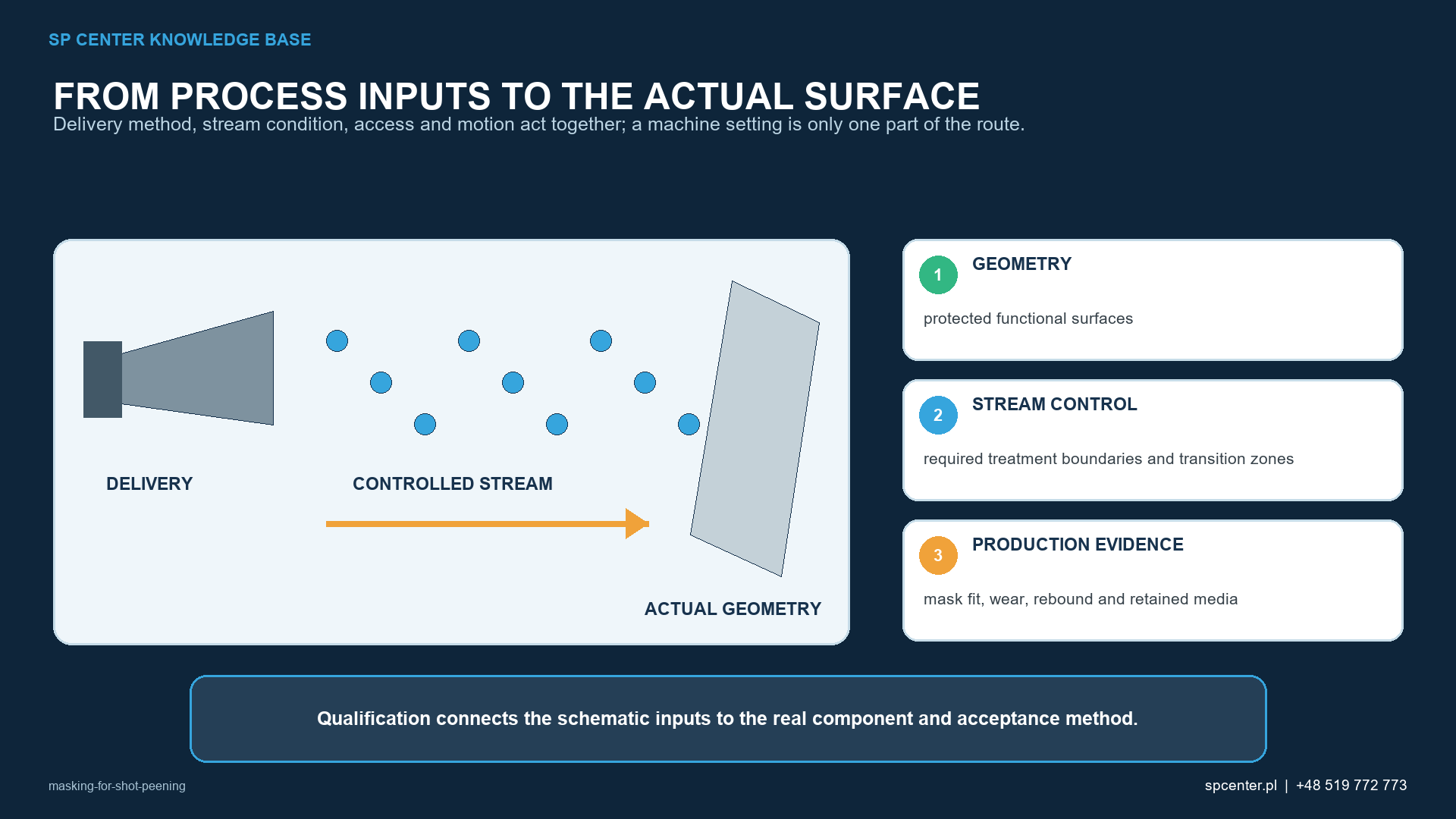
Why must masking control both sides of the boundary?
| Side of the boundary | Required condition | Typical evidence |
|---|---|---|
| Peen area | Qualified stream reaches the complete specified surface | Coverage at the boundary and least-accessible location plus invoked component acceptance |
| No-peen area | No unacceptable impact, contamination, residue, tooling mark or functional change | Visual, surface, dimensional or functional inspection required by the plan |
| Transition zone | Physical transition and boundary position remain within the authorised location and tolerance | Qualified mask geometry, installation position and boundary inspection |
| Masking interface | Mask remains retained and does not shed, loosen, trap media or damage the component | Tool condition, installation and post-removal inspection records |
Table 1. A successful mask protects the excluded surface and the required treatment at the same boundary.
A fatigue-critical fillet may sit beside a bearing seat, thread, bore, datum or sealing face. The treated zone requires the invoked intensity and coverage; the adjacent functional surface may require a controlled finish, fit or contact condition. Protecting one by under-treating or damaging the other is not an acceptable result.
Does the feature type decide whether it is masked?
No. Some drawings intentionally require treatment of threads, fastener holes, bores or internal surfaces. Operators must not infer treatment scope from geometry or past practice. Treatment, no-peen and transition zones come from the controlled drawing, invoked specification, authorised clarification and approved process plan.
How are threads, holes and functional surfaces protected?
| Feature | Masking risk | Required review |
|---|---|---|
| External thread | Cap, nut or sleeve can shadow a run-out or fillet; impacts can alter flanks, roots, crests and fit | Drawing scope, engagement depth, boundary, retention and adjacent coverage |
| Internal thread | Plug can protrude, loosen, shed or trap media | Threaded/expanding tool fit, end position, removal and protected-thread inspection |
| Blind hole | Media entry and entrapment can create contamination or blockage | Protection, tool removal and documented media-free condition |
| Through-hole or cross-hole | Shot can pass to an opposite face or protected cavity | Complete trajectory, both entrances, internal recovery and cleaning |
| Datum, bearing seat or sealing face | Texture, indentation, adhesive residue or clamping mark can change seating and function | Surface, contact, dimensional and cleanliness acceptance as invoked |
| Required internally peened surface | Mask applied by assumption can block authorised treatment | Drawing-led scope and qualified lance, nozzle or deflector route |
Table 2. Feature function, complete media trajectory and required adjacent coverage determine the masking route.
For a thread, installation depth may become a controlled dimension because excessive protrusion can shadow an adjacent run-out or fillet. For a through-hole, protecting one entrance may not prevent shot from reaching an opposite surface. For a datum, absence of peening marks is insufficient if the mask leaves a scratch, indentation or residue that changes seating.
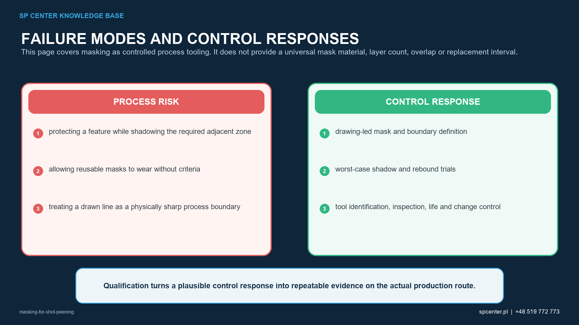
Why are shadowing, rebound and leakage different failure modes?
Shadowing blocks direct access to a surface that must be treated. Rebound redirects particles from the mask toward the component and can change local angle, impact population or surface condition. Leakage allows unintended impacts under or through a mask. Media entrapment and tool shedding create additional cleanliness risks.
Evaluate the mask edge with nozzle or wheel-stream direction, stand-off, impact angle, component motion and media trajectory. Inspect coverage at the boundary and least-accessible specified location, not only the easiest open face.
Can a physical boundary be infinitely sharp?
A drawing can show a precise line, while the mechanical transition may include complete impacts, partial impacts, rebound and a gradual change in indentation population. Requirements should define the authorised boundary position, tolerance or permissible transition. Moving a mask for manufacturing convenience needs formal engineering approval.
NASA TP-2711 examined a demarcation line on a specific Ti-6Al-4V bending-fatigue specimen related to compressor-blade work. The reported result is application-specific; it does not establish that every boundary, material, geometry or loading condition is acceptable.
How should a masking system be selected?
| Mask system | Potential strength | Principal controls |
|---|---|---|
| Rigid cap, plug, sleeve or shield | Repeatable geometry and serial durability | Retention, protrusion, rebound, edge wear, component contact and correct revision |
| Elastomeric cap, plug or sleeve | Conformity and rapid installation on irregular features | Material compatibility, tearing, lifting, ageing, shedding, fit and reuse limit |
| Qualified masking tape | Flexible boundary for flat or low-volume applications | Surface preparation, approved material, thickness/layers, overlap, adhesion, lifting and residue |
| Sacrificial plate or insert | Replaceable impact-absorbing boundary | Position, retention and replacement before erosion changes the boundary |
| Integrated fixture shield | Combines location and protection in a production setup | Fixture datum, wear, contamination, rebound and interaction with stream access |
Table 3. No masking family is universally superior; the complete qualified configuration is application-specific.
Do not state universal tape type, layer count, overlap or replacement interval. Exposure severity, media, angle, component surface, adhesive compatibility, temperature, cleaning route and functional requirements determine the qualified choice.
How are reusable masks controlled?
| Control point | What to define | Failure prevented |
|---|---|---|
| Tool identification | Unique ID, revision, applicable part/revision and status | Use of a plausible but incorrect mask |
| Installation | Orientation, engagement depth, end position, retention and error-proofing | Boundary shift, loosening, leakage or incorrect loading |
| Pre-use inspection | Cleanliness, fit, edge geometry, cracks, deformation, wear and retention features | Use beyond the qualified condition |
| Replacement criterion | Measured wear, cycle limit or condition-based rejection | Progressive leakage, boundary drift or increased shadowing |
| Process interaction | Nozzle/wheel direction, stand-off, angle, motion, mask edge, rebound and trapped-media route | Qualification of the mask in isolation from the stream |
| Post-process verification | Protected surface, boundary, adjacent coverage, residue, loose media and dimensions as invoked | Acceptance merely because the mask survived |
| Change control | Review triggers for material, supplier, design, position, life, part or process change | Silent transfer outside the qualified configuration |
Table 4. Tool control maintains the masking condition demonstrated during qualification.
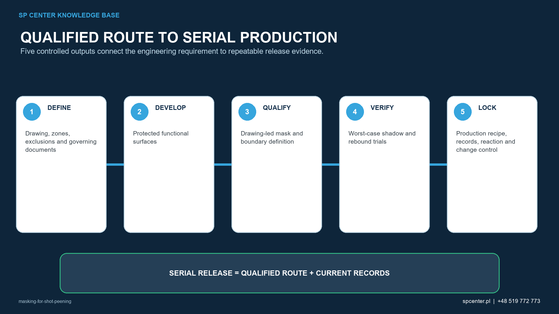
What should post-process verification cover?
- No unacceptable evidence of peening, contamination or tooling damage on protected surfaces.
- Boundary position and transition within the drawing or process-plan requirement.
- Required coverage immediately beside the mask and at critical, least-accessible geometry.
- No adhesive, elastomer or tool residue; no trapped debris or loose media.
- Acceptable threads, datums, sealing faces, bearing seats, bores and other functional surfaces.
- Dimensions, roughness, contact condition and cleanliness where explicitly invoked.
What is masking for shot peening?
Masking is controlled process tooling that protects drawing-defined no-peen areas and establishes treatment boundaries while preserving required stream access and coverage on the peened side.
Which surfaces should be masked?
Only the controlled drawing, invoked specification and approved process plan determine scope. Threads, holes, datums, bearing seats and sealing faces are not automatically masked or automatically peened.
Can a shot peening mask create a perfectly sharp boundary?
The drawing may define a line, but the physical transition can include full and partial impacts, rebound and a changing impression population. The permitted location, tolerance or transition zone must be defined and qualified.
Does an untouched no-peen area prove the mask is acceptable?
No. The required peened area may be shadowed, the boundary may have shifted, or the mask may have scratched, indented or contaminated the protected surface. Both sides and the interface require inspection.
Should threads always be masked?
No. Some designs require treatment of threaded or fastener-related features. Never infer treatment scope from feature type; use the controlled engineering documentation.
Can a reusable mask stay in service until it breaks?
No. Erosion, edge wear, deformation or loss of fit can move the boundary before complete failure. Use qualified inspection and measurable or condition-based replacement criteria.
Does correct Almen intensity prove masking is acceptable?
No. Almen intensity verifies standardised stream response. Boundary position, adjacent coverage, protected-surface condition, residue, trapped media and functional acceptance require component-level evidence.
What should a masking RFQ include?
Provide the drawing and revision, treatment/no-peen/transition zones, material and surface condition, specifications, intensity and coverage, geometry, quantities, functional and dimensional limits, and required records.
Key takeaways
- Treat masks as qualified process tooling, not consumable housekeeping.
- Control the no-peen side, the transition and coverage on the peened side.
- Define scope from approved engineering documentation, not from feature type.
- Evaluate shadowing, rebound, leakage, trajectory and media entrapment separately.
- Identify and inspect reusable tools; replace them before wear moves the boundary.
- Include mask design and installation in process qualification and change control.
Related SP Center guides
Technical sources
1. SAE AMS2430U: Shot Peening, revised April 2018
2. SAE ARP7488: Peening Design and Process Control Guidelines, issued January 2018
3. SAE J2277_202301: Shot Peening Coverage Determination, revised January 2023
4. SAE J443_202512: Procedures for Determining and Verifying Peening Intensity, revised December 2025
5. SAE J2441_202511: Shot Peening, stabilized November 2025
6. Carek, Shot Peening for Ti-6Al-4V Alloy Compressor Blades, NASA TP-2711
Standards note: Use the complete revisions invoked by the drawing, contract and customer flow-down. This guide does not create a universal mask material, boundary tolerance or replacement interval.
Author: Paweł Kmieć
Discuss masking and treatment-boundary requirements: +48 519 772 773 | [email protected]