


Define treatment, transition and exclusion zones, then qualify mask wear, fixture position, stream access, local motion and boundary inspection
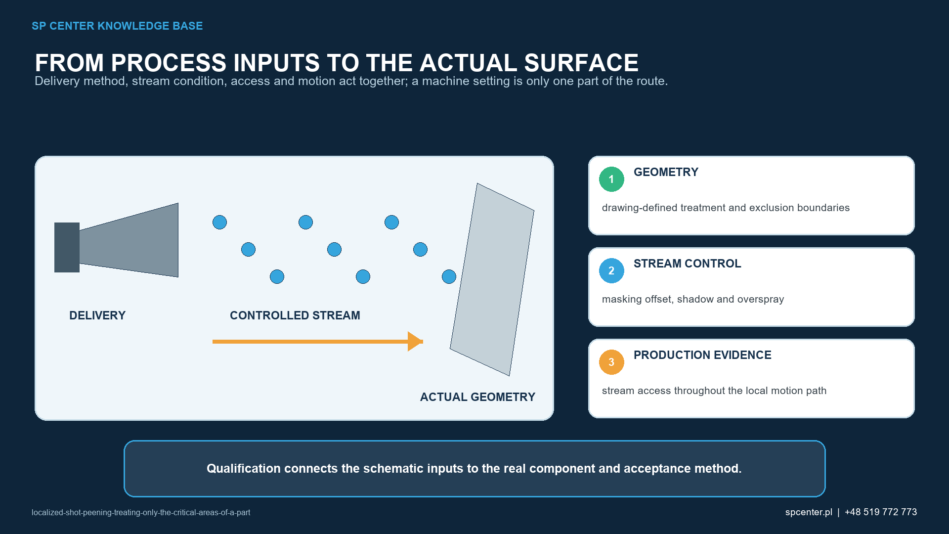
Localized shot peening treats only drawing-defined regions of a component while adjacent areas are protected or limited to an approved transition. The engineering challenge is not simply reducing area. The real boundary depends on mask position and wear, media scatter, stream angle, stand-off, fixture datum and motion. A controlled localized route must therefore demonstrate intensity, coverage, boundary position and protection of excluded surfaces separately.
What must the drawing define?
| Drawing input | Why it matters | Clarification if missing |
|---|---|---|
| Treatment zone and datum | Locates the required peened surface | Obtain dimensioned boundaries from the design authority |
| Exclusion zone | Protects threads, fits, sealing surfaces, coatings or other sensitive features | Define whether zero impact evidence or a tolerated transition applies |
| Boundary tolerance | Allows inspection of actual mask and stream variation | Do not create an internal tolerance without approval |
| Transition or blend requirement | Controls whether a gradual exposure change is required | Do not assume every boundary must be sharp or gradual |
| Intensity and coverage | Defines separate process and surface acceptance results | State strip designation, coverage definition and applicable methods |
| Surface and dimensional limits | Prevents the localized route from damaging an adjacent function | Identify roughness, distortion, cleanliness or other invoked checks |
Table 1. The supplier converts controlled component data into tooling and motion; it does not invent the functional boundary.
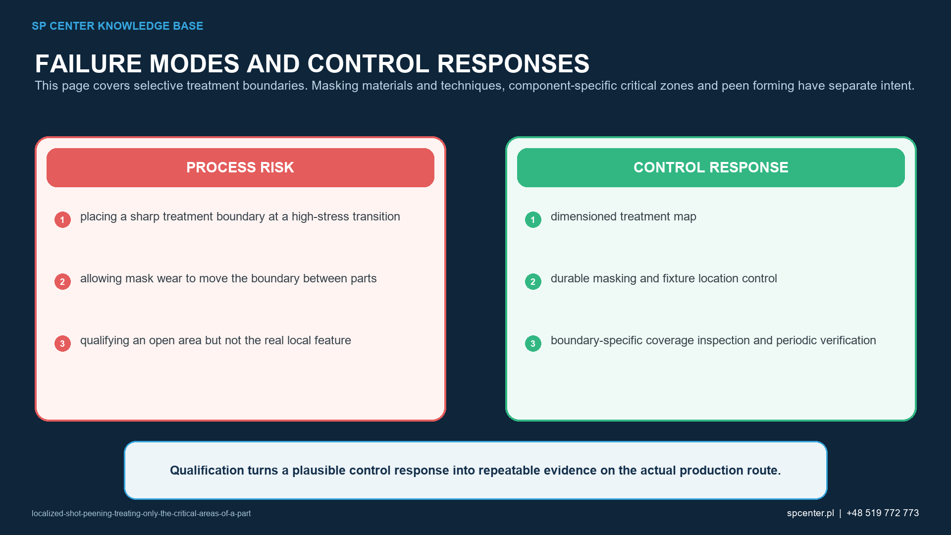
A boundary placed at a highly stressed transition may need design review, but that does not mean every sharp boundary is prohibited. The design or repair authority decides where the treatment starts and ends and whether a transition band is required.
How do masks change the actual treated area?
A mask blocks direct impact but also casts a shadow into the nominal treatment zone. Scattered particles can travel beyond the mask edge. Thickness, edge shape, gap, attachment, erosion and rebound therefore affect both undercoverage and unintended impacts.
Qualify the mask material for durability, contamination risk and removal. Define its reference to component datums and its inspection or replacement limit. “Apply tape to the line” is not a repeatable manufacturing instruction unless material, method and tolerance are controlled.
Which equipment and motion variables control the boundary?
| Control element | Qualification question | Serial check |
|---|---|---|
| Mask | Does material, thickness and edge survive exposure without contamination or movement? | Identity, position, condition and approved wear limit |
| Fixture and datums | Does the part repeat relative to mask and stream? | Correct fixture, seating, clamp and position confirmation |
| Nozzle or wheel pattern | Does the qualified footprint reach all required local features? | Configuration, stand-off, orientation and physical condition |
| Programmed motion | Are speed, path, overlap, indexing and direction representative? | Approved program revision and cycle completion |
| Media delivery | Are intensity and footprint stable across the local path? | Media condition, flow and applicable equipment parameters |
| Inspection | Can centre, edge, transition and exclusion zones be distinguished? | Approved coverage and boundary method with required records |
Table 2. The boundary is a coupled output of part location, protection, media stream and programmed exposure.
For a pneumatic route, nozzle distance and angle can change footprint and shadow. For a wheel route, the component position relative to the throw pattern is decisive. The two methods are not automatically interchangeable. The production setup must match the qualified configuration.
How are intensity and coverage verified locally?
Use the applicable Almen strip, holder and saturation method to verify the standardized intensity condition at defined representative positions. This does not prove access or coverage on a hidden local feature.
Coverage is assessed on the specified component surface. Examine the centre, least accessible feature, boundary and any required transition. An indirect fluorescent or tracer method needs approval, qualification and correlation to the applicable direct acceptance basis.
How is the boundary recorded?
The plan states the datum, measurement or observation method, magnification and lighting where relevant, sampling, acceptance tolerance, record form and authority. Photographs or mapped coordinates are useful only when they are required and traceable; they are not a universal substitute for the drawing-defined method.
If the near-boundary residual-stress or roughness gradient is a design concern, qualify that response with a suitable method. Coverage alone cannot quantify residual-stress magnitude or depth.
Which nonconformities require containment?
| Observed result | Possible cause | Controlled response |
|---|---|---|
| Undercoverage near mask edge | Mask shadow, adverse angle or insufficient path overlap | Contain and review access, path and qualified mask offset |
| Impacts beyond exclusion boundary | Mask gap, wear, movement or scattered media | Inspect sensitive surface and restore approved masking condition |
| Boundary moves between parts | Datum, seating, clamp or mask wear is unstable | Stop production and verify fixture capability and affected lots |
| Correct intensity but poor local coverage | Almen location does not represent component access | Add component-specific access and coverage evidence |
| Mask residue or embedded foreign material | Incompatible mask or cleaning route | Use approved material and contamination disposition |
| Repeat exposure proposed as correction | Local cumulative exposure is unknown | Obtain explicit rework authority and renewed acceptance plan |
Table 3. A boundary failure is investigated before additional exposure is considered.
Identify batches processed since the last acceptable mask, fixture and program check. Preserve the actual mask, settings, alarms and inspection evidence. Release requires the applicable technical or customer disposition when a functional zone or excluded surface may be affected.
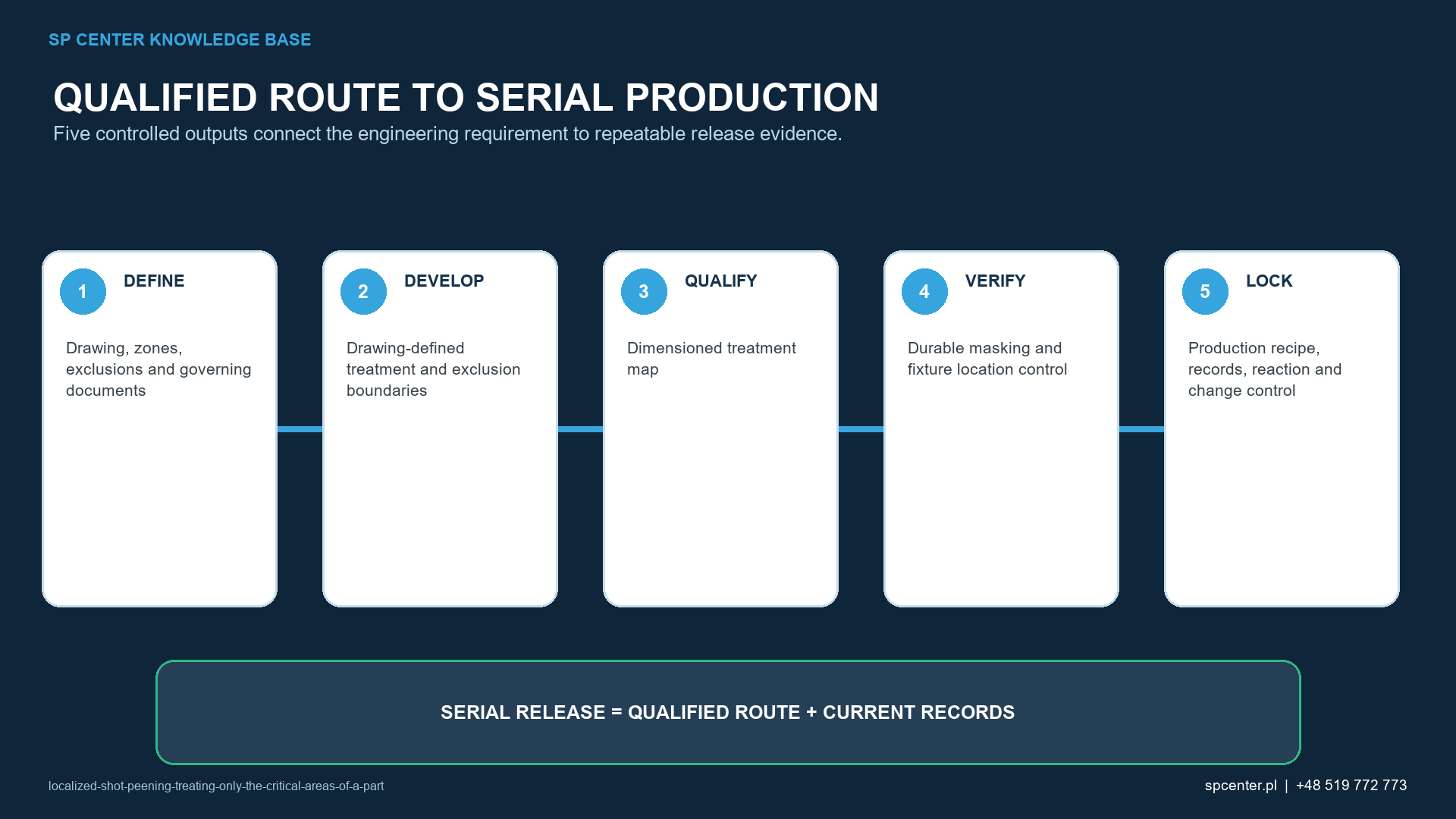
How is the localized route qualified?
- Freeze drawing, treatment map, standards and customer flow-down.
- Select production-representative equipment, media, fixture, mask and component geometry.
- Challenge the least accessible required zone and the most sensitive exclusion boundary.
- Verify standardized intensity and component-specific coverage as separate outputs.
- Confirm surface, dimensions, cleanliness and transition response when invoked.
- Approve the configuration, serial checks, wear limits, records and change triggers.
Changes in mask material, thickness, datum or wear limit can be as significant as a nozzle or program change. Assess effect before production resumes.
What should an RFQ contain?
Provide part and drawing revision, material and heat treatment, incoming surface, dimensioned treatment, transition and exclusion zones, invoked standards, intensity and strip designation, coverage definition, surface and dimensional limits, quantity, lot logic and required records. Include CAD or a marked drawing when boundary geometry cannot be described unambiguously.
SP Center can review feasibility and propose tooling and process-control evidence. Missing functional boundaries or acceptance authority must be clarified by the responsible design or customer organisation.
Frequently asked questions
What is localized shot peening?
It is controlled peening of drawing-defined areas while adjacent zones are excluded or receive only the approved transition. It still requires qualified intensity, coverage, media, equipment, motion and records.
Is localized peening the same as manual spot peening?
No. Localized describes the treatment area, not an automatically approved delivery method. Hand peening or another route is permitted only when the governing requirements and qualification allow it.
Must a treatment boundary always be sharp?
No. The design or repair authority defines the boundary and any transition or tolerance. A supplier should not invent a sharp edge or blend where the controlled data is silent.
How is the boundary inspected?
Use the approved method and drawing datum to assess required, transition and excluded zones. Direct visual, magnified, photographic or qualified tracer evidence may be used only as allowed by the governing plan.
Does an Almen strip prove the localized area is covered?
No. Almen intensity characterizes the standardized stream at the defined test location. Component access, coverage and boundary position require separate evidence.
Can tape alone define the process?
No. A mask is one control element. Its material, thickness, position, wear, attachment, contamination behaviour, fixture relationship and stream shadow must be qualified.
When is requalification needed?
Assess changes to treatment map, part geometry, mask, fixture, machine, nozzle or wheel, media, program, motion, load, inspection method or surface sequence for their effect on the qualified boundary and results.
What information is required for quotation?
Provide the controlled drawing with datums, treatment, transition and exclusion zones, material and heat treatment, surface condition, intensity, coverage, surface and dimensional limits, standards, quantity and required records.
Key takeaways
- Localized peening is defined by controlled treatment and exclusion zones, not by a casual spot operation.
- Mask shadow and scattered media can move the actual boundary in opposite directions.
- Fixture datum, stream footprint and motion must remain in the qualified configuration.
- Almen intensity does not prove local component coverage.
- Boundary, transition and excluded surfaces need an approved inspection basis.
- Repeat exposure requires explicit rework authority.
Related SP Center guides
Technical references
1. SAE AMS2430U: Shot Peening, revised April 2018
2. SAE ARP7488: Peening Design and Process Control Guidelines, issued January 2018
3. SAE J442_202602: Tools for Peening Intensity Determination and Verification, revised February 2026
4. SAE J443_202512: Procedures for Determining and Verifying Peening Intensity, revised December 2025
5. SAE J2277_202301: Shot Peening Coverage Determination, revised January 2023
Standards note: Use the complete revisions invoked by drawing and contract. This guide does not create a treatment boundary, tolerance or rework permission.
Author: Paweł Kmieć
Discuss a localized shot peening requirement: +48 519 772 773 | [email protected]