


Define a multidimensional, evidence-based operating region that accounts for interactions and meets intensity, coverage and component acceptance simultaneously
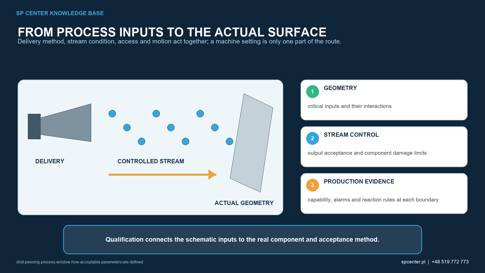
A shot peening process window is the approved combination of material state, media, delivery energy, stream geometry, motion, exposure and equipment condition that produces every required result. It is not a collection of unrelated minimum and maximum values. If pressure, media flow, nozzle distance and traverse are each acceptable separately but their combined corner was never assessed, the permitted recipe may still contain a nonconforming condition.
How does a process window differ from a recipe?
A recipe records the nominal configuration used to run a part. The process window defines the qualified region around that configuration. Production operating limits may be narrower than the demonstrated qualification boundary to provide a justified margin for process and measurement variation.
The drawing, governing specification and customer requirements remain the source of mandatory acceptance. A development study cannot silently widen an intensity range, change media or replace a specified coverage requirement. Any alternative requires the applicable engineering and customer authorization.
| Variable class | Examples | How it is handled |
|---|---|---|
| Material and part state | Alloy, heat treatment, hardness, incoming roughness, geometry and prior operations | Define the qualified family and prohibit unassessed substitutions |
| Media state | Material, size distribution, hardness, shape, operating mix, contamination and replenishment | Set procurement, operating-mix, inspection and reaction limits |
| Energy and delivery | Air pressure, wheel speed, media mass flow, nozzle or wheel condition and stream profile | Study interactions and control the actual equipment route |
| Geometry and motion | Distance, angle, traverse, rotation, dwell, indexing, fixture position and shadowing | Qualify the treatment map and representative worst-access features |
| Equipment and environment | Machine identity, wear, air quality, separator efficiency, temperature and maintenance state | Define baseline condition, preventive controls and change triggers |
| Response and acceptance | Almen intensity, coverage, roughness, dimensions, damage, residual stress and representative fatigue | Use multiple responses; no single output substitutes for the others |
Table 1. The window links controlled inputs, disturbance variables and several independent responses.
Which responses must define acceptability?
At minimum, use the process outputs required by the controlled job: normally Almen intensity and component coverage, together with specified surface, damage, dimensional and cleanliness limits. Depending on the application, qualification may also include roughness, profile, residual-stress depth, distortion, microstructure, coating compatibility or representative fatigue performance.
A parameter combination is acceptable only if all required responses conform. High compressive residual stress does not excuse excessive roughness; complete coverage does not excuse a chipped edge; a valid Almen result does not prove access to a recessed feature.
Why must parameter interactions be assessed?
Air pressure changes particle acceleration, but its effect depends on nozzle geometry, air capacity, media mass flow, media size, hose condition and distance. Wheel speed interacts with media flow, blade condition, hot-spot position and part motion. Traverse speed interacts with stream width, overlap and the number of passes.
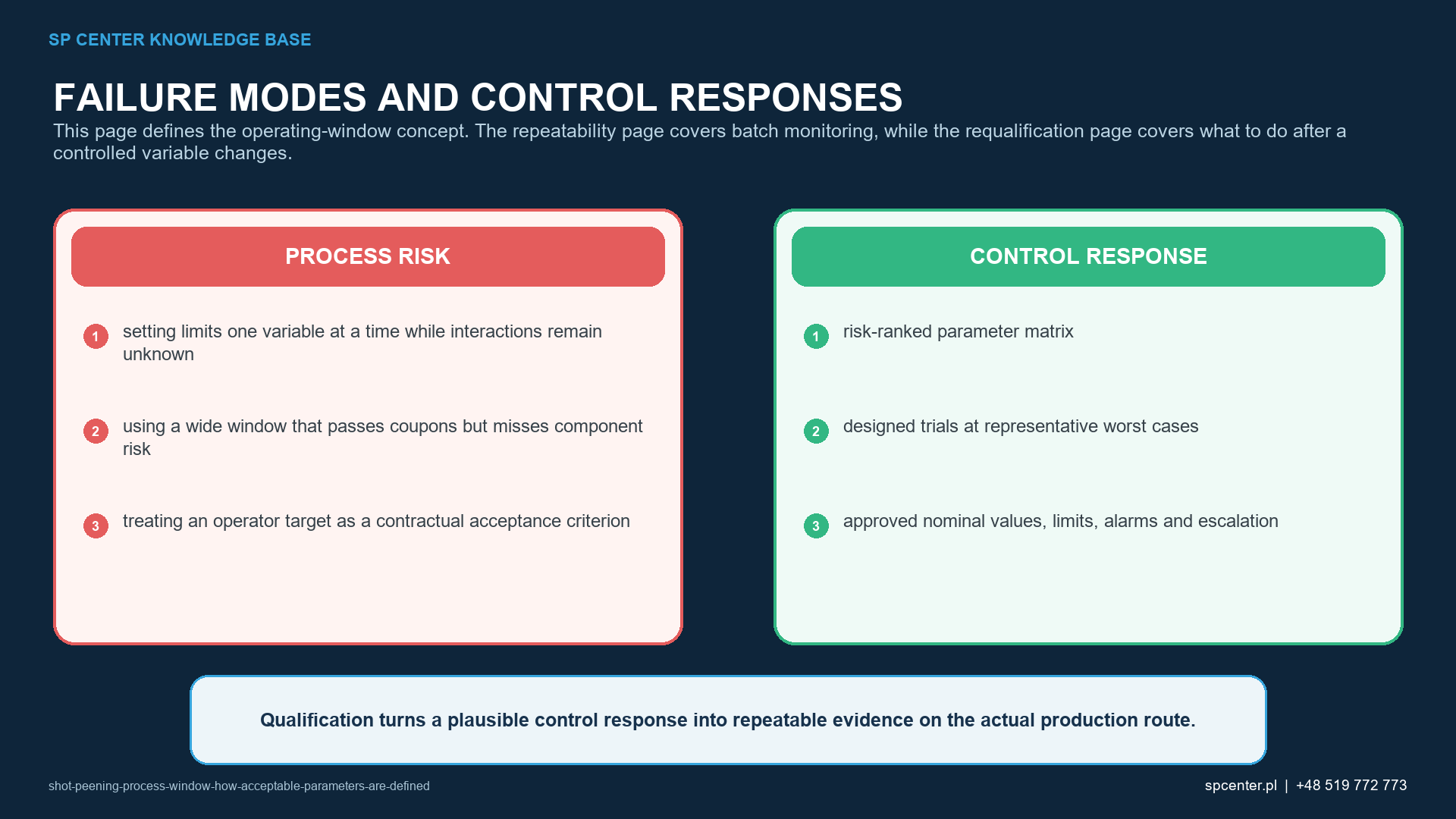
Changing one factor at a time can miss these interactions and can produce contradictory limits. Structured engineering trials or design of experiments can estimate main effects, interactions and curvature, provided the factor ranges are technically safe and the measurements are capable.
How is a defensible process window developed?
| Qualification phase | Required work | Decision evidence |
|---|---|---|
| 1. Scope and requirements | Identify part family, drawing, specification, critical zones, exclusions and service claim | Approved problem statement and acceptance matrix |
| 2. Measurement readiness | Confirm resolution, bias where relevant, repeatability and reproducibility for critical measurements | Measurements can distinguish meaningful process differences |
| 3. Risk and variable screening | Map failure modes, interactions, practical constraints and safe trial ranges | Prioritized factors and protected trial plan |
| 4. Structured development | Use engineering trials or DOE to estimate main effects, interactions and curvature within safe bounds | Candidate region supported by data rather than one-factor assumptions |
| 5. Boundary and confirmation trials | Challenge relevant boundary combinations on representative material and geometry with containment | Every claimed boundary meets all acceptance criteria with repeat runs |
| 6. Release and capability | Select nominal settings and operating limits, confirm repeatability and document change authority | Approved recipe, control plan and traceable qualification report |
Table 2. Window development proceeds from requirements and measurement readiness to controlled production release.
Boundary trials do not mean sending valuable parts blindly to every mathematical extreme. Trials require risk review, safe stop criteria, suitable specimens or sacrificial parts, product containment and approved dispositions. Test the combinations that support the claimed region, including relevant low-low, low-high and other interaction corners where technically meaningful.
How are Almen intensity and saturation used?
SAE J442 and J443 define the tools and procedures for determining and verifying peening intensity. SAE J2597 addresses computer-generated saturation curves. A valid curve belongs to a defined Almen arrangement and exposure sequence and must be evaluated under the applicable requirements.
Intensity data can show the response of the stream to selected inputs, but the Almen strip is not the component. Component geometry, material, hardness, incidence angle and fixture access can change local response. Use Almen control as one layer of the window, not as the complete application qualification.
How are coverage and component condition included?
SAE J2277 addresses coverage determination. The qualified window must show that the complete treatment zone reaches the specified coverage without unacceptable cumulative exposure, missed shadowed areas or processing of excluded zones. A multi-position or multi-pass route must be assessed as a total exposure history.
Surface roughness, dimensional change, edge integrity and cleanliness often create the upper practical boundary before Almen intensity does. This is why the strongest or fastest setting is not automatically the most robust production setting.
What is the role of measurement capability and uncertainty?
A narrow window cannot be defended with a measurement system whose variation is comparable to the allowed range. Resolution, repeatability, reproducibility, calibration status, sampling location and operator method must be suitable for the decision. Where bias or destructive sectioning is relevant, reference methods and specimen preparation also need control.
Qualification boundaries should be stated with the data, repeat runs and uncertainty used to support them. An operating margin may then be placed inside the boundary according to risk and capability. There is no universal ten-percent or similar guard band.
How is the approved window transferred to production?
| Production element | What must be defined | Required reaction |
|---|---|---|
| Nominal recipe and revision | Machine, program, fixture, media, sequence, setpoints and part family | Prevent use of an obsolete or unapproved configuration |
| Operating limits | Monitored limits for critical inputs and outputs, including sampling and data frequency | Alarm, stop or contain according to the approved reaction plan |
| Media control | Lot identity, operating-mix condition, replenishment, separator and contamination checks | Segregate media and product when identity or condition is uncertain |
| Equipment verification | Nozzles, wheels, flow controls, sensors, motion, fixtures, maintenance and calibration status | Restore verified condition and assess product since the last acceptable check |
| Part release | Intensity, coverage, surface, dimensional, cleanliness and record requirements | Do not use a conforming Almen result to override failed component acceptance |
| Change control | Triggers for review, limited confirmation or full requalification | Obtain authorization before using the changed configuration in production |
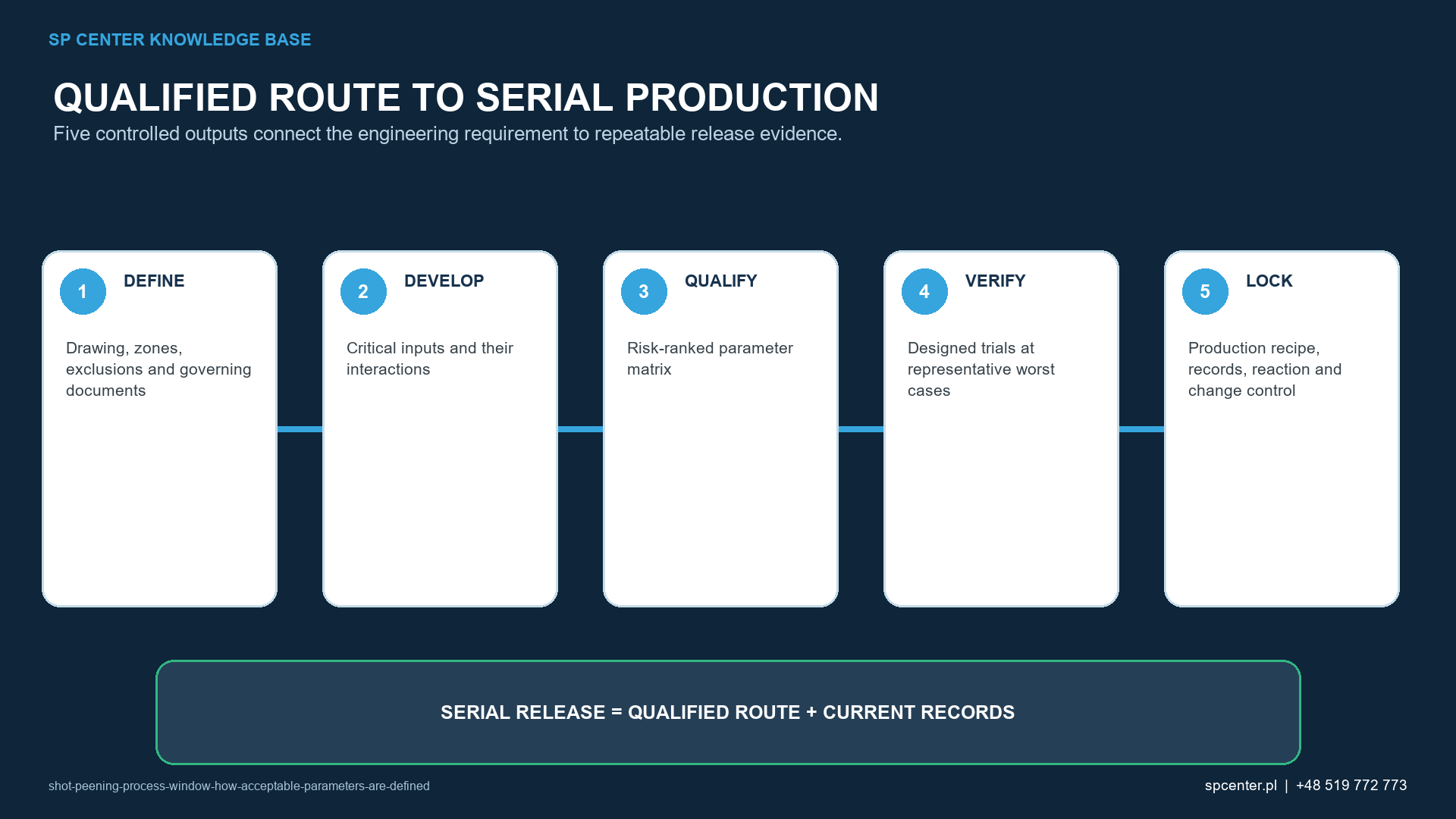
Table 3. Qualification becomes production control only when recipe, monitoring and reaction rules are linked.
Computer monitoring improves traceability only when sensor locations, scaling, alarm logic, data retention and bypass control are qualified. A recorded pressure or flow value does not prove the sensor was measuring the relevant condition or that the nozzle and fixture were correctly positioned.
Which changes challenge the process window?
Changes to machine, nozzle, wheel, air supply, media source or size, operating-mix control, program, robot path, fixture, part geometry, material condition, heat treatment, masking, inspection method or governing requirement can challenge the evidence. The approved change procedure decides whether document review, limited confirmation or full requalification is necessary.
Do not average a changed condition into routine production data. Identify the exact change, assess affected variables and interactions, contain unassessed product and obtain authorization before release.
What should the qualification record contain?
- Controlled drawing, specification revisions, part family and treatment map.
- Material, heat treatment, media and equipment baseline.
- Measurement-system evidence and calibration status.
- Risk analysis, trial design, raw data, exclusions and stop criteria.
- Saturation curves, coverage records and component acceptance results.
- Statistical or engineering analysis, boundary rationale and repeat confirmations.
- Approved nominal recipe, operating limits, monitoring and reaction plan.
- Change triggers, authorization, report revision and retained records.
State what was not tested and where engineering judgement was used. A transparent limited window is safer than a broad undocumented claim.
Frequently asked questions
What is a shot peening process window?
It is the approved multidimensional region of material, media, equipment, energy, geometry, motion and exposure conditions that meets every defined process and component acceptance criterion.
Is a process window the same as a list of machine tolerances?
No. Independent tolerances can permit an untested combination. A process window accounts for relevant interactions and boundary combinations.
Does a valid Almen intensity define the process window?
No. It is one response. Coverage, surface and dimensional condition, damage limits and any required application evidence must also conform.
Must every possible parameter combination be tested?
Not necessarily. Use risk analysis, process knowledge and an appropriate experimental design to select informative and safe combinations, then confirm the claimed boundaries.
Why are nominal setpoints usually inside the qualification boundary?
An internal operating margin can absorb normal measurement and process variation. Its size must follow evidence, capability and risk, not a universal percentage.
Can a window developed on flat coupons be used for complex parts?
Only when representativeness is demonstrated. Access, angle, fixture contact, curvature, edge response and local acceptance can require component or surrogate confirmation.
What happens when one parameter is outside its operating limit?
Follow the approved reaction plan: stop or alarm as required, contain affected product, restore the verified state, assess records and obtain authorized disposition.
When does a process-window change require requalification?
Review changes to machine, delivery system, media, program, fixture, material family, geometry, specification or acceptance method under the approved change-control rules before production use.
Key takeaways
- A process window is multidimensional and interaction-aware.
- Every required output must conform at the claimed boundary.
- Separate qualification boundaries, nominal settings and production operating limits.
- Verify the measurement system before interpreting small process differences.
- Use controlled boundary trials and representative geometry.
- Link the approved window to monitoring, reaction and change control.
Related SP Center guides
- Optimizing Shot Peening Parameters with Design of Experiments
- How Machine Condition Affects Process Quality
- Shot Peening Fixtures
- Shot Peening Saturation Curve
Technical references
1. SAE ARP7488: Peening Design and Process Control Guidelines, issued January 2018
2. SAE AMS2430U: Shot Peening, revised April 2018
3. SAE AMS2432E: Shot Peening, Computer Monitored, revised October 2022
4. SAE J2441_202511: Shot Peening, stabilized November 2025
5. SAE J442_202602: Tools for Peening Intensity Determination and Verification, revised February 2026
6. SAE J443_202512: Procedures for Determining and Verifying Peening Intensity, revised December 2025
7. SAE J2597_201709: Computer Generated Shot Peening Saturation Curves
8. SAE J2277_202301: Shot Peening Coverage Determination, revised January 2023
10. Tange, Study on Optimizing a Shot-Peening Process, SAE 2005-32-0087
Standards and evidence note: The technical papers concern their stated media, spring materials or applications. They illustrate variable interaction and optimization, not a universal process window. Use complete controlled job requirements.
Author: Paweł Kmieć
Discuss a shot peening process-window study: +48 519 772 773 | [email protected]