


How measurement tools, intensity procedures and component acceptance fit together in a controlled shot peening route
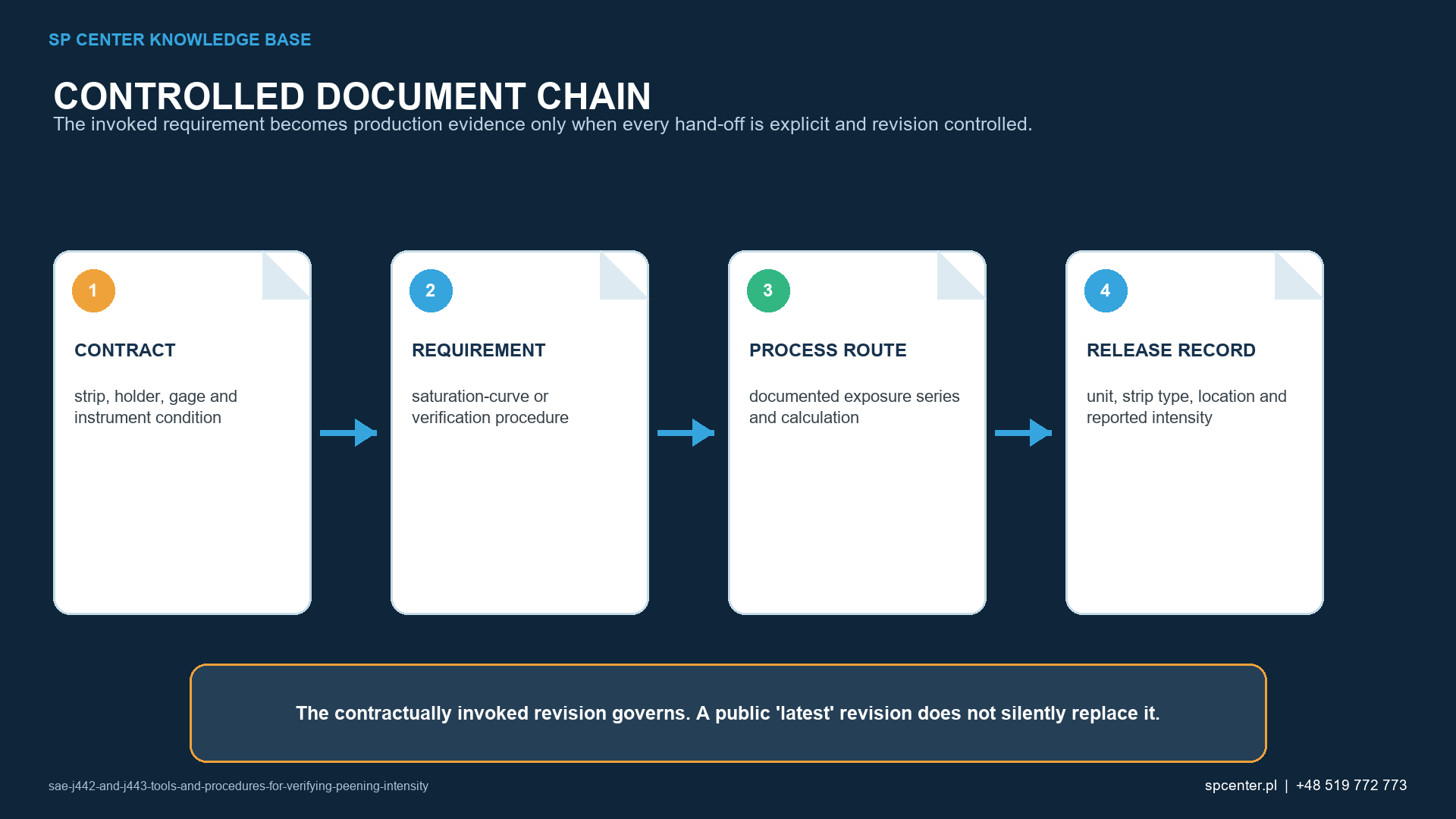
SAE J442 and SAE J443 perform different but complementary roles. J442 defines requirements for equipment and supplies used to measure peening intensity, while J443 defines the procedure for deriving and verifying the intensity exerted on a surface. Neither document turns an Almen result into proof of component coverage, residual stress or fatigue life. A defensible process keeps the measurement system, peening configuration, component inspection and engineering validation connected but technically separate.
What does each document contribute?
| Document role | Primary engineering question | Typical controlled elements |
|---|---|---|
| SAE J442 | Are the equipment and supplies suitable for intensity determination and verification? | Almen strips, holders, gages and associated requirements identified by the current invoked edition |
| SAE J443 | How is peening intensity derived and verified under a controlled procedure? | Measurement sequence, saturation or verification route, result evaluation and records |
| SAE J2597 | How may a computer-generated saturation curve be evaluated? | Input data, approved calculation route, curve result and review |
| Part or customer specification | Which intensity, location, frequency and acceptance requirements apply? | Drawing zones, strip designation, limits, supplements and release requirements |
Table 1. The contractual drawing and specification hierarchy determines which revision, limits, frequency and customer supplements apply. The controlled standard must be consulted for detailed requirements.
What is Almen intensity actually telling you?
An Almen strip responds to a peening stream by developing curvature that is measured as arc height after the defined exposure and handling route. The intensity decision represents the effect of that stream under standardized reference conditions. It is not a direct measurement of media velocity, impact energy, component residual stress or surface coverage.
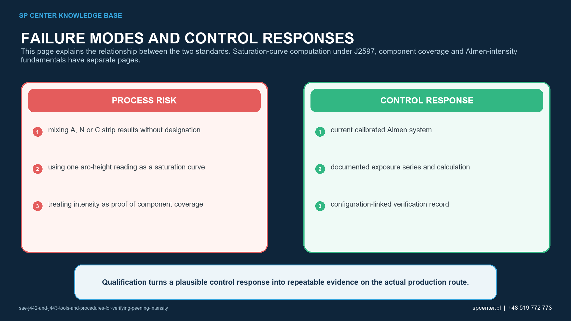
Comparable results require more than the same numerical machine setting. Strip designation and condition, holder, gage, mounting position, nozzle or wheel geometry, media, distance, angle, motion and exposure all affect the measurement chain. A result without configuration traceability is difficult to defend during qualification, audit or nonconformance review.
How should the Almen measurement system be controlled?
- Confirm the invoked revisions, strip designation, required intensity range, verification location and frequency.
- Use strips, holders, gages and supporting equipment that meet the applicable controlled requirements.
- Inspect and identify the strip and holder, and verify the gage condition and status before measurement.
- Install the holder in the approved position and reproduce the qualified peening configuration.
- Perform the required intensity-determination or verification sequence without unapproved parameter changes.
- Record the raw readings, result, configuration, acceptance decision and any investigation or repeat measurement.
Detailed conditioning, measurement and acceptance steps must come from the invoked edition of J442, J443 and the customer process specification. Where the documents conflict or a required supplement is missing, the work should be held for controlled technical clarification.
What is the difference between determining and verifying intensity?
Intensity determination establishes the intensity for a defined peening-stream configuration using the applicable saturation-curve procedure. Routine verification checks whether the approved process continues to deliver the required intensity at the defined verification condition. The governing process specification determines when each route is required and how results are accepted.
A single verification result should not be treated as a timeless machine property. Wear, media condition, pressure or wheel-speed variation, nozzle or wheel changes, fixture movement and maintenance can alter the stream. Reaction plans must define containment, investigation, restoration and required re-verification.
Which failures invalidate the measurement result?
| Control point | Failure mechanism | Required response |
|---|---|---|
| Test strip | Wrong designation, damage, mishandling or uncertain identity | Do not use the result; segregate and repeat with conforming material |
| Holder and location | Incorrect orientation, mounting, access or unapproved position | Restore the approved configuration and repeat the affected verification |
| Gage and reading | Dirty contact surfaces, unstable seating, incorrect zeroing or invalid status | Stop, inspect the measurement system and repeat as required |
| Peening configuration | Changed pressure, flow, wheel speed, nozzle, distance, angle, media or motion | Contain affected production and follow the approved reaction and requalification path |
Table 2. A conforming numerical result does not excuse an invalid measurement system or an unapproved configuration.
Which evidence layers must remain separate?
| Evidence | What it demonstrates | What remains separate |
|---|---|---|
| Saturation-curve intensity determination | The derived intensity for the defined peening-stream configuration | Component coverage and surface acceptance |
| Routine intensity verification | Repeatability of the peening stream at the approved verification condition | Residual-stress profile and fatigue performance |
| Coverage inspection | Impact coverage of the required component surface by the approved method | Conformance of the Almen measurement system |
| Component validation | Required component response for the qualified material, geometry and process route | Automatic acceptance of later production without the specified controls |
Table 3. Process verification, component surface acceptance and component validation answer different questions and must not be substituted for one another.
What should be recorded for traceability?
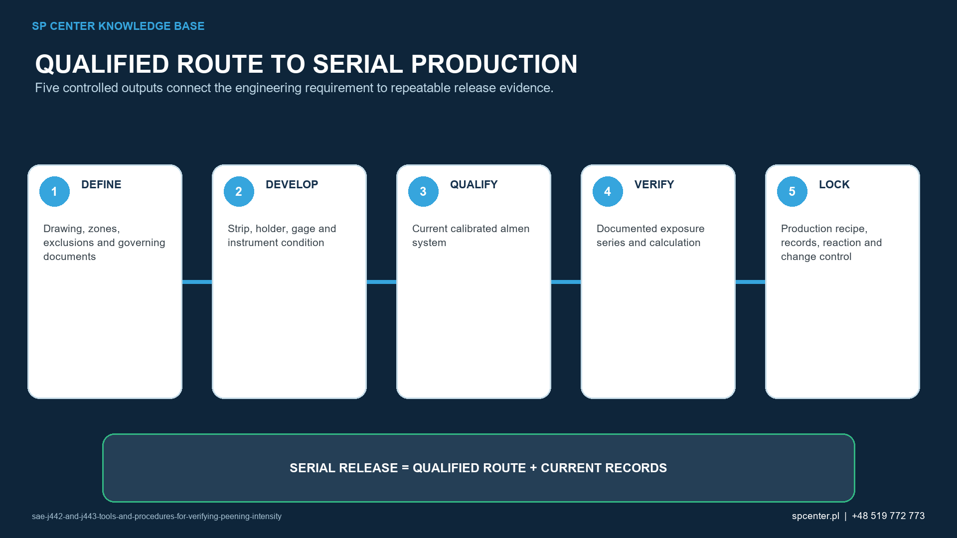
- Applicable drawing, process specification, customer supplement and document revision.
- Machine and location, fixture, holder position, nozzle or wheel configuration and programmed motion.
- Media identification and condition, pressure or wheel speed, air and media flow where applicable, distance and angle.
- Strip designation and identity plus required holder and gage status.
- Raw readings, exposure values, saturation-curve or verification result, units and acceptance decision.
- Operator or system identity, date and time, deviations, repeats, maintenance and reaction-plan actions.
Frequently asked questions
What is the difference between SAE J442 and J443?
J442 addresses tools and supplies used for peening-intensity determination and verification. J443 addresses the procedures used to derive and verify the intensity. The invoked revisions and customer documents determine the exact requirements.
Does an Almen strip measure residual stress in the component?
No. It provides a standardized response to the peening stream. Component residual stress is a different characteristic and requires a separate measurement or validation route when specified.
Does correct intensity prove 100% coverage?
No. Intensity and coverage are independent acceptance characteristics. Coverage must be inspected on the required component surface by the approved method.
Can one Almen result be transferred to another machine or fixture?
Not by assumption. The result belongs to a defined configuration and location. Transfer requires review against the approved procedure and applicable qualification rules.
May J2597 software replace J442-compliant equipment?
No. Computer generation evaluates measured data; it does not replace conforming strips, holders, gage control or a valid physical measurement sequence.
What should happen after an out-of-limit verification?
Affected production should be contained and the approved reaction plan followed. The investigation must address the measurement system, peening configuration, time window, product impact and required re-verification or requalification.
Key takeaways
- J442 controls the tools and supplies; J443 controls the procedure for determining and verifying intensity.
- Almen intensity characterizes the peening stream under a defined reference configuration, not the complete component response.
- Strip, holder, gage, location and process settings form one controlled measurement chain.
- Intensity, coverage and component performance are separate evidence layers.
- Out-of-limit or invalid measurements require containment and a documented reaction, not a convenient repeat without investigation.
Related SP Center guides
- SAE J2597: Computer-Generated Saturation Curves
- Almen Intensity in Shot Peening
- Shot Peening Coverage
Technical references
1. SAE J442_202602: Tools for Peening Intensity Determination and Verification, revised February 2026
2. SAE J443_202512: Procedures for Determining and Verifying Peening Intensity, revised December 2025
3. SAE J2597_201709: Computer Generated Shot Peening Saturation Curves
4. SAE J2277_202301: Shot Peening Coverage Determination, revised January 2023
Standards note: Verify the current publisher status and use the complete revisions invoked by the drawing, contract and customer requirements.
Author: Paweł Kmieć
Discuss your shot peening requirement: +48 519 772 773 | [email protected]